5 power connection, Power connection – Daktronics GPR-12EV-RGB User Manual
Page 14
8
Power Installation
3.5 Power Connection
Power is terminated either internally to the
power termination board or externally to the J
box.
Terminating single-phase power to the
internal power termination panel:
1. Open the display as explained in
Section 6.2 and locate the power
termination panel.
2. Route the cable through conduit to the
back of the display. Remove the rubber
plug from the ¾” (1.905 cm) hole for
access, being careful not to damage
internal components.
3. If larger conduit is required, remove
metal filings from display after drilling.
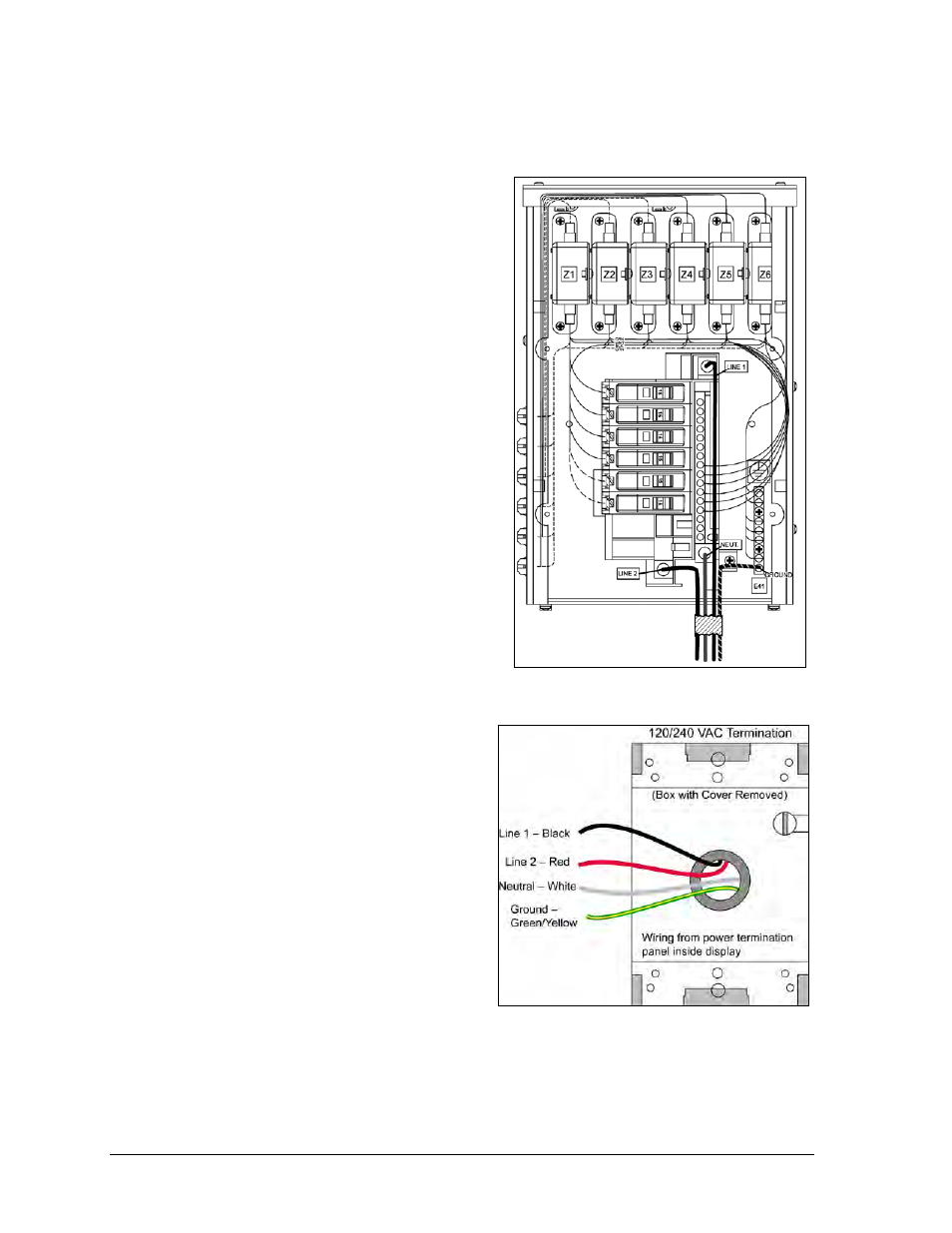
4. Connect the neutral wire to the neutral
lug and the live wires to Line 1 and
Line 2. Refer to Figure 8.
5. The ground wire connects to the
grounding bus bar.
Terminating hot, neutral, and ground wires at
the J box
1. Route the power cable through
3
/
4
"
conduit to the rear of the display and
into the power termination J box.
2. The power termination enclosure
contains two or three wires plus a
ground coming from the interior of
the display. These wires are pre-
terminated to the power termination
panel inside the display.
3. Inside the external J box, shown in
Figure 9, connect the power wires to
the wires coming from the display
interior using wire nuts.
Figure 8: 120/240 V Single-Phase Power
Termination
Figure 9: 120/240 VAC Power Termination