3 mlc diagnostics, 4 temperature sensor diagnostics, 5 troubleshooting display problems – Daktronics GPR-12EV-RGB User Manual
Page 28: Module and led problems, Mlc diagnostics, Temperature sensor diagnostics, Troubleshooting display problems
22
Diagnostics and Troubleshooting
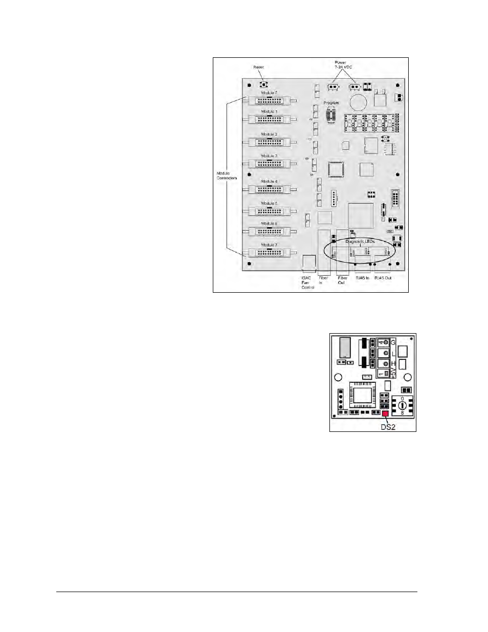
7.3 MLC Diagnostics
Each multi-line controller (MLC)
contains four red diagnostic
LEDs on the lower right side of
the controller, as shown in
Figure 23. When fiber is properly
connected, the LED labeled DS23
(left side) will be off and the
other LEDs will be on.
7.4 Temperature Sensor
Diagnostics
If the display includes a
temperature sensor, the
temperature sensor board will
provide diagnostic information.
The temperature sensor board,
shown in Figure 24, is located
inside the temperature sensor
housing which hangs near the
display. A flashing DS2 LED
indicates that the unit is sending temperature information. It also
indicates that the unit has power.
Refer to Appendix B for temperature sensor mounting and
connections.
7.5 Troubleshooting Display Problems
Some common symptoms that may be encountered in a display
and simple steps to resolve them follow. Solutions are organized
by priority, so try them in order.
Troubleshooting may require removing or replacing modules.
Refer to Section 6.2 for instructions on this procedure. Make sure
power and signal cables are reconnected correctly and latches are
tightly closed when replacing modules.
Make sure the first module is receiving power.
Consult the Venus
®
1500 software Help file when content problems (including brightness,
message, temperature, and testing) occur. Click the Application button in the top left corner
of the Venus
®
1500 Home page and click Help.
Module and LED problems
One or more LEDs will not light
Figure 23: MLC Diagnostic LEDs
Figure 24: Temperature
Sensor Board