5 temperature interconnection (rare use) – Daktronics GPR-12EV-RGB User Manual
Page 71
Temperature Sensor Mounting For
GalaxyPro Revolution Displays
page 3 of 4
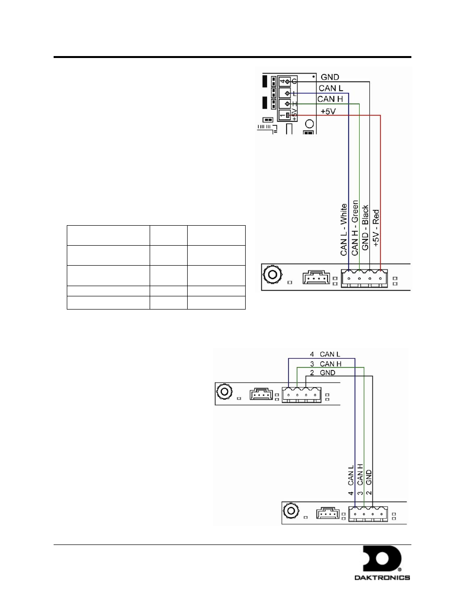
5. Connect the cable coming from the
controller’s terminal block to the
temperature sensor board in the
temperature sensor housing. Refer to
Figure 5 and the following table for
wiring locations and connections at the
sensor and to the controller.
Figure 5: CAN Temperature Sensor Connection -
M4 Controller
6. Route cable around the sensor board as
shown in Drawing A-197884.
7. Connect the cable and reassemble the
sensor.
Note: The cable length from the sensor to the
last display should not exceed 500 feet.
Primary – Controller
Board (A31-TB1)
Field
Cabling
CAN Temp
Sensor (TB1)
Pin 1 (+5V CAN)
Red
Pin 1
(+5V CAN)
Pin 2 (GND CAN)
Shield
Black
Pin 4
(GND CAN)
Pin 3 (CAN H)
Green
Pin 2 (CAN H)
Pin 4 (CAN L)
White
Pin 3 (CAN L)
1.5 Temperature Interconnection
(rare use)
In a primary to primary
configuration, a 4-conductor
shielded cable is needed to
terminate the temperature sensor
from one display to the other.
One end terminates at the 4-position
terminal block (TB1) on the primary
display. The other end terminates at
the 4-position terminal block (TB1)
in the second display. Refer to
Figure 6
and the following table for
correct interconnect locations.
Note: Do not connect the wire to
pin one on either display.
In a primary to primary
configuration, a 4-conductor
shielded cable is needed to
Figure 6: CAN Controller Interconnect – M4 Controller
DD1514799 Rev 0
29 January 2009
201 Daktronics Drive PO Box 5128, Brookings, SD 57006-5128
tel: 866-343-3122 fax: 605-697-4700
www.daktronics.com