3 lifting a display or display section, General lifting notes, 4 optional temperature sensor mounting – Daktronics GPR-12EV-RGB User Manual
Page 10: Lifting a display or display section, Optional temperature sensor mounting
4
Mechanical Installation
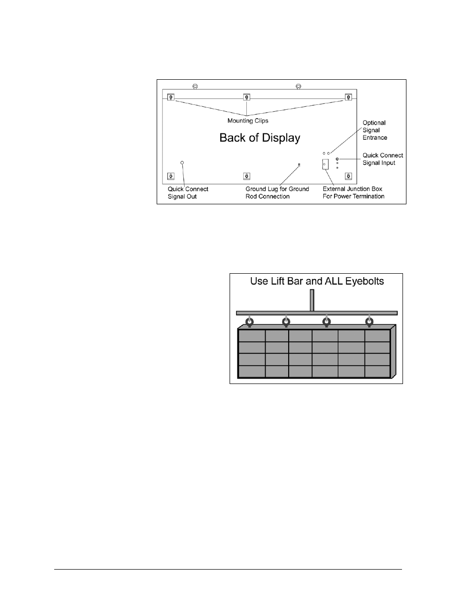
Also remember the location of mounting clips and the clearance needed for the power/signal
terminations on
the back of the
display and
ventilation system
on the front of the
display, as shown
in Figure 4 and
Figure 5. Display
height and wind
loading are also
critical factors to
consider. Find this
information on the
Shop Drawing
which was
supplied with the
order.
2.3 Lifting a Display or Display Section
Maintain a 90-degree angle between the
cabinet and lifting method to retain the
cabinet’s structural integrity.
If damage occurs due to improper lifting
procedures, the warranty will be void.
General Lifting Notes:
Lift the display into position on the
support structure using a lifting bar and
all eyebolts, as shown in Figure 6.
Do not attempt to permanently support
the display by the eyebolts.
After installation is complete, carefully inspect the display for any holes that may allow water
to seep into the display and seal them with silicone.
If the eyebolts on the top of the display were removed, plug the holes with bolts and the
rubber-sealing washer that was removed with the eyebolt.
Refer to Section 3 for power routing and to the appropriate communication manual for
signal connections to the display.
2.4 Optional Temperature Sensor Mounting
If an optional temperature sensor is used with this display, refer to Appendix B for mounting
and signal connections.
Figure 5: Back Section
Figure 6: Lifting the Display