Light sensor replacement – Daktronics GPR-12EV-RGB User Manual
Page 35
Parts Replacement
29
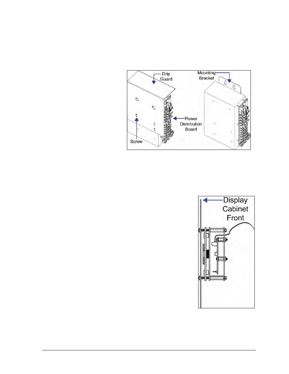
4. Loosen the screw(s) holding the drip guard to the power supply and lift the drip
guard up and off the power supply.
5. Loosen the screw holding the power supply bracket to the cabinet upright and lift it
up and off the hooks.
Power supplies for
16mm displays
feature their
mounting bracket on
the rear of the power
supply.
6. Carefully pull the
power supply out of
the cabinet.
7. Move the new power
supply into place and
tighten the screw on
the support bracket.
8. Reconnect all the
plugs so that each module receives power, and plug the ISAC fan control back in.
Refer to the appropriate Layout Drawing for module connections, if needed.
Light Sensor Replacement
The light sensor assembly is mounted inside the bottom left
edge of the cabinet. Refer to Figure 13 for location. The entire
assembly fits over two screws.
If the light sensor fails, only the circuit board must be replaced.
Remove the bottom left module to access the light sensor.
To replace a light sensor circuit board, shown in Figure 30:
Tool required: #2 Phillips screwdriver
1. Remove the screws that hold the light sensor to the
cabinet.
2. Unplug the light sensor from the controller and plug
the new one in.
3. Reattach the new circuit board, following these steps in
reverse.
Align the new circuit board so the lens lines up with
the
1
/
2
" circular opening in the bottom left edge of the
display.
Figure 29: 16mm Power Supply
Figure 30: Light Sensor
Assembly