3 pmsi interface example – Comtech EF Data CRS-170A User Manual
Page 90
CRS-170A L-Band 1:1 Redundancy Switch
MN/CRS170A.IOM
Cables and Connections
Revision 13
5–20
5.3.2.3 PMSI Interface Example
The Pre-Mapped Symbol Interface (PMSI) is an EIA-485 point-to-point bus system where one
device transmits, and the other device on the bus is configured to receive. It is a function
associated with DoubleTalk
®
Carrier-in-Carrier
®
(CnC
®
) that permits the modulator in a selected
unit to provide a direct copy of its output (the outbound interferer) to the Offline modem in a
1:1 pair. The Offline modem then takes the PMSI signal and uses it for its own CnC
®
reference.
You must take specific configuration steps to enable CnC
®
in your CDM-625/A 1:1 pair before
you can make any switch configurations, This ensures proper operation of the pair within a
configured CRS-170A 1:1 Redundancy System.
Chapter 4. MODEM
AND
SWITCH
CONFIGURATION
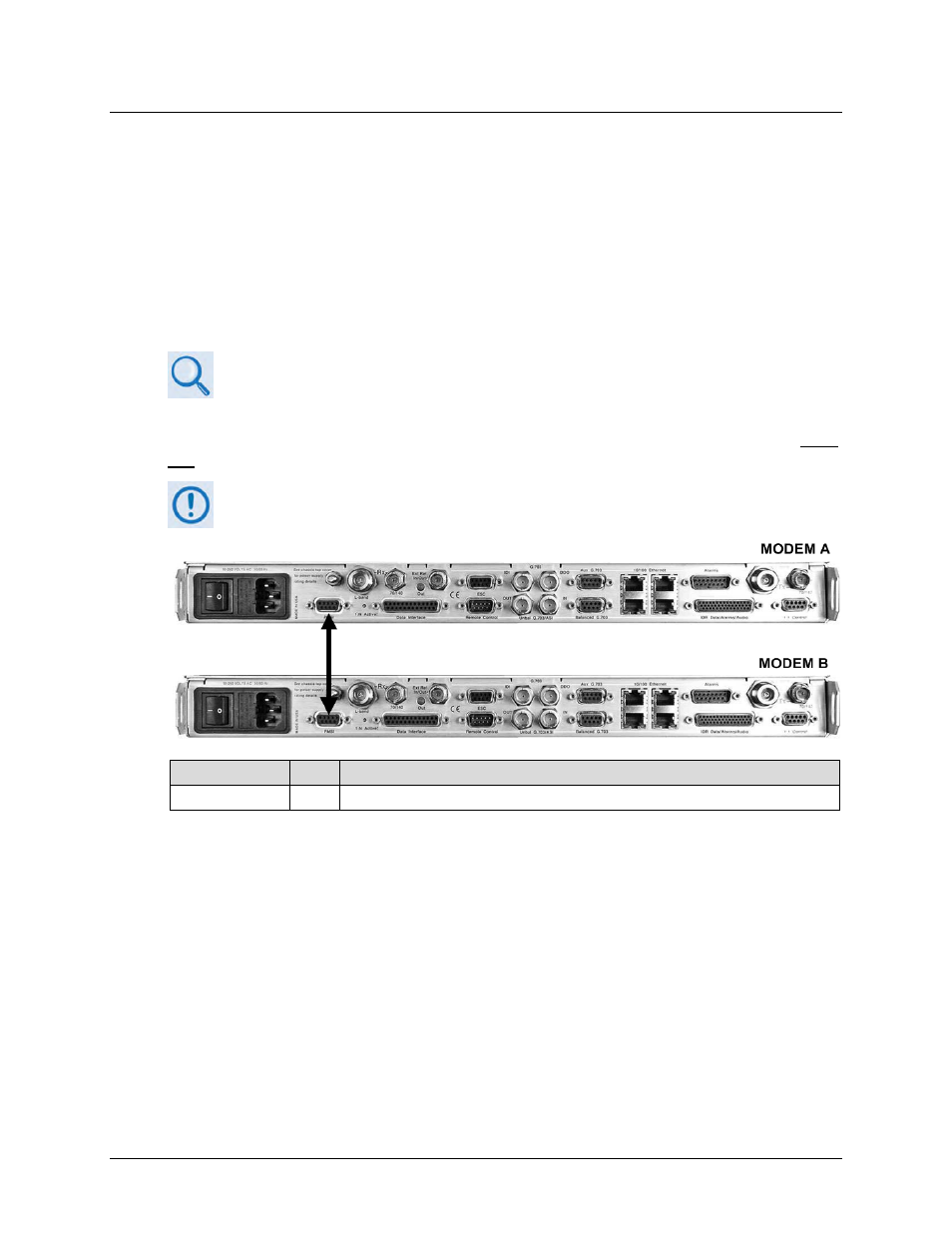
Use of PMSI requires that you connect and secure the CDM-625/A Multi-drop CnC
®
Plus 1:1
Cable CA-0000276 (2X DB-9M, 1’) between the Redundant Modem and the Traffic Modem using
CnC. See Figure 5-17.
The CA-0000276 Multi-Drop CnC PLUS 1:1 Cable bypasses the CRS-170A L-Band 1:1
Redundancy Switch.
CEFD Part No.
Qty
Description
CA-0000276
1
CDM-625/A Data Cable – Shielded, Multi-drop CnC
®
Plus, 1:1, (2X) DB-9M, 1’
Figure 5-17. CDM-625/A PMSI 1:1 Example