Comtech EF Data CRS-170A User Manual
Page 73
CRS-170A L-Band 1:1 Redundancy Switch
MN/CRS170A.IOM
Cables and Connections
Revision 13
5–3
5.2 Common CRS-170A 1:1 Redundancy Control / IF Interface Cabling
Kits
When assembling a Comtech EF Data 1:1 Redundancy System, in addition to purchasing the
desired modem pair (one Traffic Modem, one Backup Modem), you must also purchase the
CRS-170A 1:1 Redundancy Control/IF Interface Cabling Kit tailored to your modem choice. Each
kit provides the CRS-170A L-Band 1:1 Redundancy Switch module and the control and IF cables
required for connection of the switch to the modems in the 1:1 redundancy configuration.
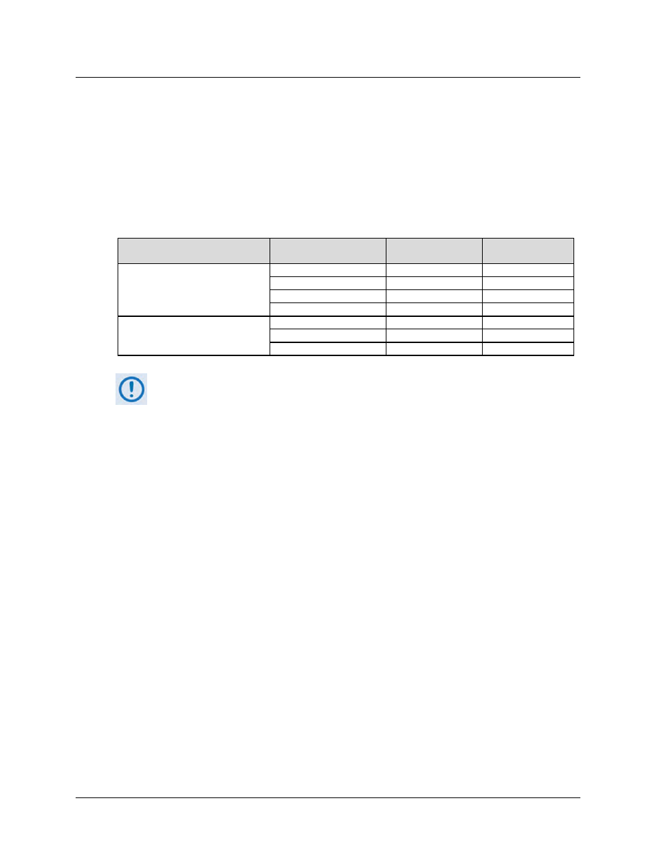
Kit usage, on a per-modem basis, is as follows:
CRS-170A 1:1 Redundancy
Control / IF Interface Cabling Kit Modem Pair
Control
Connections Figure
IF Connections
Figure(s)
KT-0000160
CDM-625 or CDM-625A
5-1
5-2, 5-3
CDM-850
5-17
5-18
CDM-840
5-22
5-23
CDM-760 or CDM-750
5-26
5-27
KT/12551
CDM-710GL
5-39
5-40
CDM-710
5-45
5-46
CDM-700
5-51
5-52
1)
The CDM-570L and CDM-570AL modems require a modem-specific redundancy
kit, CEFD P/N KT/10860-1. See Sect. 5.7.1 for further information.
See Figure 5-59 in Sect. 5.11 for cabling requirements for the CDM-600L (CLM-
9600) Open Network Satellite Modems.
See Figure 5-60 in Sect. 5.12 for cabling requirements for the SDM-300L3
Satellite Modems.
2)
Separately sold kits are available to facilitate connection from the modem to
various user terrestrial data interfaces, excluding Ethernet (which require user-
provided CAT5 Ethernet cables and Layer 2 switches). Examples of such kit usage
are provided in the “Modem-to-User Data Interface Connections and Examples”
sections for each modem in this chapter.