Comtech EF Data CRS-170A User Manual
Page 108
CRS-170A L-Band 1:1 Redundancy Switch
MN/CRS170A.IOM
Cables and Connections
Revision 13
5–38
5.6.2.3 Non-IP Data Interface Kit and Connection Examples
While different data interface cards may be installed into both PIIC (Plug-In
Interface Card) slots, only one data interface type is operable at a given time. The
data interface combinations allowable in the CDM-760/-750 chassis PIIC Slots 1
and 2 are as follows:
PIIC Slot 1
PIIC Slot 2
G.703 E3/T3
None
None
G.703 E3/T3
You will need separate cabling kits for each CDM-760/-750 non-IP data interface configuration.
Each user data interface requires one interface kit per 1:1 modem pair. For example, Figure 5-32
in Sect. 5.6.2.3.1 identifies the interface kit and its quantities that you will use for the G.703 PIIC
data interface.
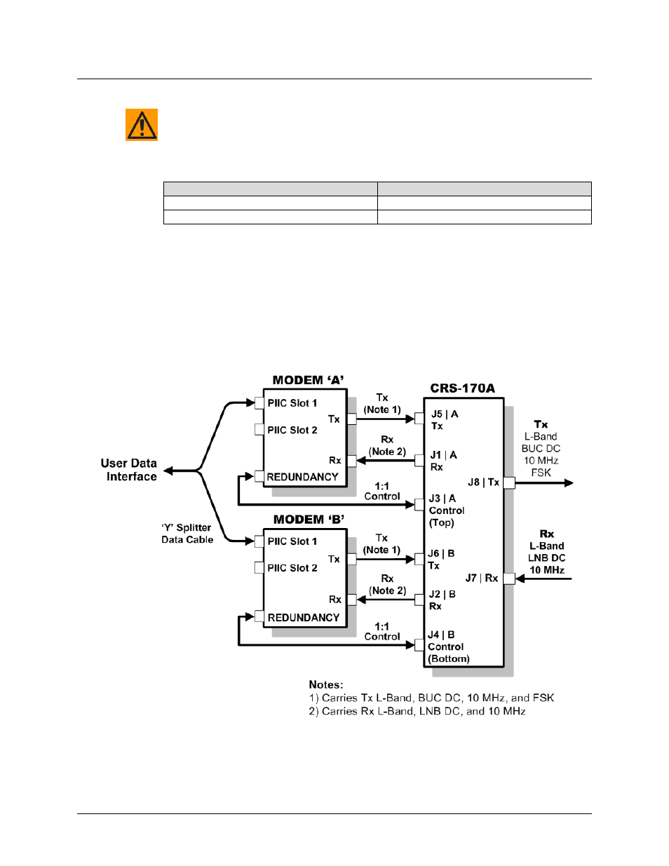
Figure 5-31 shows the block diagram that is typical for the kits shown in this section. Note that
this diagram does not apply to the default Gigabit Ethernet data interface configuration (Figure
5-29), which requires user-provided Ethernet cables and Layer 2 switches.
Figure 5-31. CDM-760/-750 Block Diagram – UserModemSwitchTraffic