1 gigabit ethernet data interface example – Comtech EF Data CRS-170A User Manual
Page 106
CRS-170A L-Band 1:1 Redundancy Switch
MN/CRS170A.IOM
Cables and Connections
Revision 13
5–36
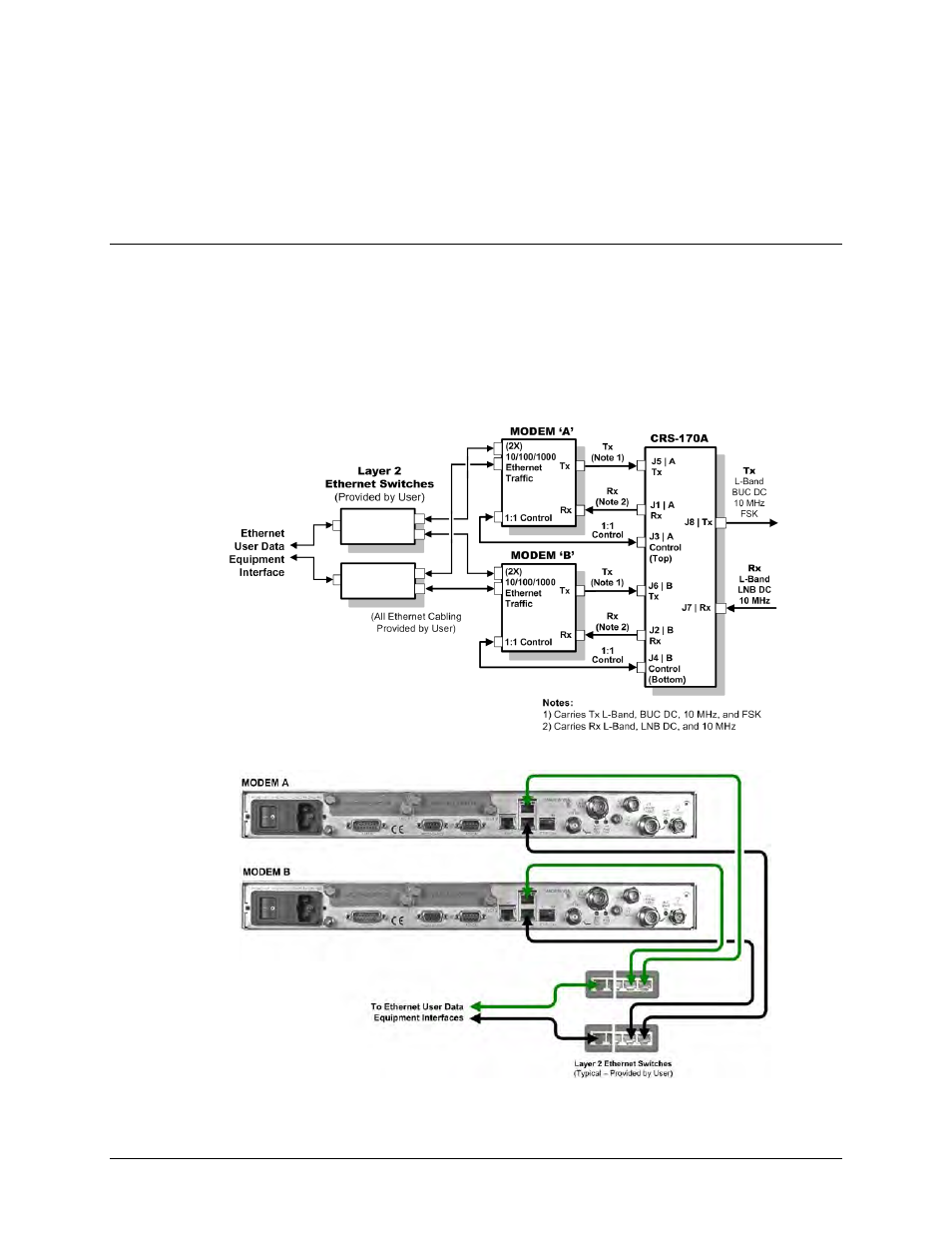
5.6.2 Modem-to-User Data Interface Connections and Examples
In addition to the control and IF Modem-to-Switch cabling shown previously, a number of data
interface configuration kits are available for use with the CDM-760 and CDM-750 High-Speed
Trunking Modems.
5.6.2.1 Gigabit Ethernet Data Interface Example
The CDM-760/-750 provides a ‘J7 | OPTICAL’ port and two Plug-In Interface Card (PIIC) slots for
optional data traffic handling. Both modems otherwise feature two 10/100/1000 Gigabit
Ethernet RJ-45 data interface ports by default. Figure 5-29 shows a block diagram and cabling
example for a CDM-760/-750 1:1 modem configuration using these RJ-45 ports (this example
shows use of both ports). This configuration requires no cabling and component kit – you must
use user-provided Ethernet cables and Layer 2 switches for direct connection to the modems.
CDM-760/-750 Block Diagram – Gigabit Ethernet 1:1 Operation
Figure 5-29. CDM-760/-750 RJ-45 Gigabit Ethernet 1:1 Example