2 crs-170a user connectors, 1 modem side connectors, 1 if connectors (50( type ‘n’) – Comtech EF Data CRS-170A User Manual
Page 46: 1 if connectors (50 ω type ‘n’)
CRS-170A L-Band 1:1 Redundancy Switch
MN/CRS170A.IOM
Switch Connectors and Pinouts
Revision 13
3–4
Connection Instructions: Press down the tab on the cable plug, and then insert the plug into the
RJ-4x jack. The connection is complete when the tab ‘clicks’ into position inside the jack.
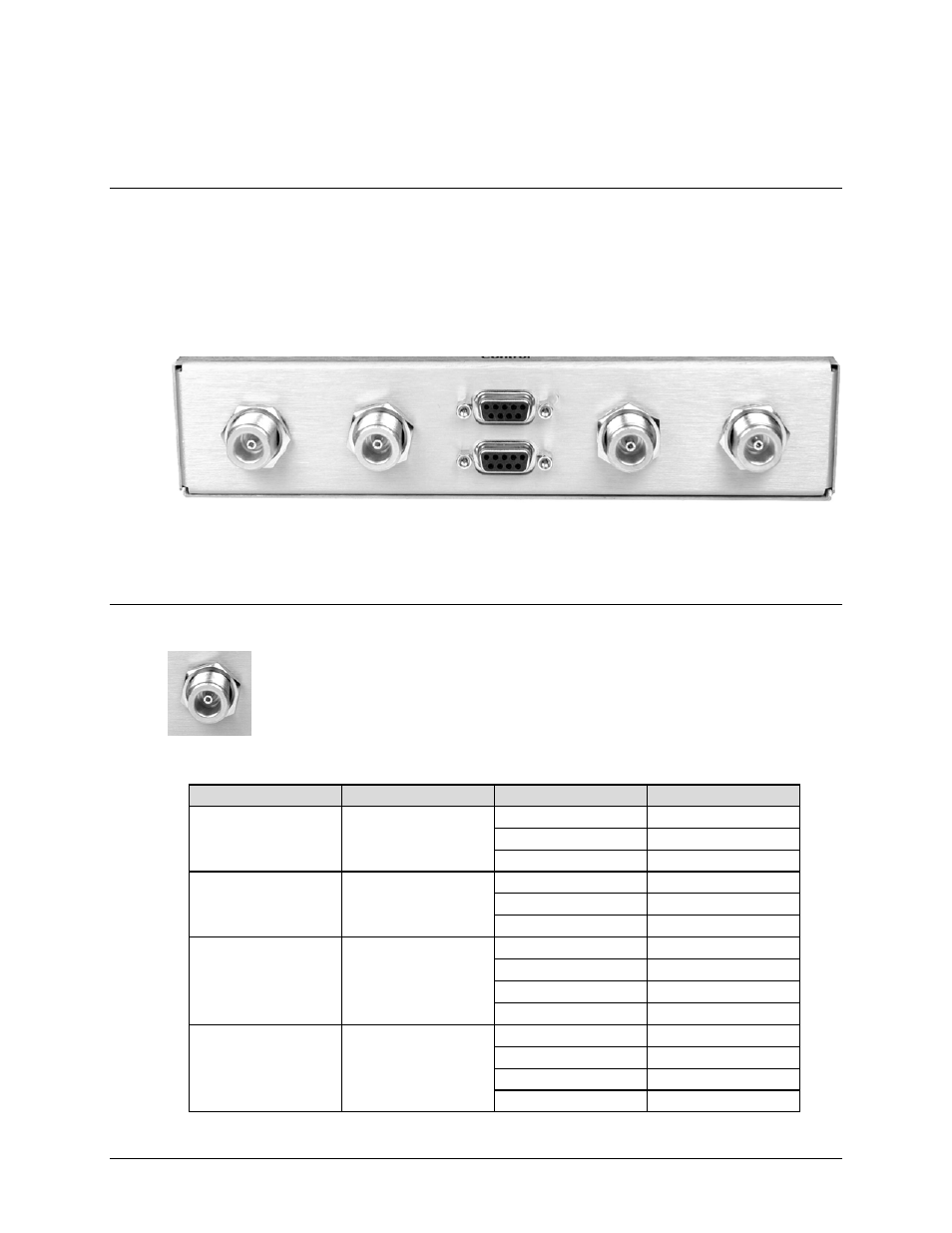
3.2 CRS-170A User Connectors
3.2.1 Modem Side Connectors
The modem side connectors (Figure 3-3) provide all necessary external connections between the
CRS-170A and the compatible Comtech EF Data modems.
J6 Tx B
J5 Tx A
J3 Control A
J4 Control B
J2 Rx B
J1 Rx A
Figure 3-3. CRS-170A – Modem Side Connectors
3.2.1.1 IF Connectors (50Ω Type ‘N’)
Four 50Ω Type ‘N’ female connectors are provided on the modem side of the
CRS-170A.
Table 3-1. Modem Side Type ‘Type ‘N’ Connectors
Ref Des
Name
Description
Direction
J1
Rx A
RX-IF signal
Out
LNB 10 MHz Ref
In
LNB Power
In
J2
Rx B
RX-IF signal
Out
LNB 10 MHz Ref
In
LNB Power
In
J5
Tx A
TX-IF signal
In
BUC 10 MHz Ref
In
BUC FSK Comm.
In/Out
BUC Power
In
J6
Tx B
TX-IF signal
In
BUC 10 MHz Ref
In
BUC FSK Comm.
In/Out
BUC Power
In