Comtech EF Data CRS-170A User Manual
Page 122
CRS-170A L-Band 1:1 Redundancy Switch
MN/CRS170A.IOM
Cables and Connections
Revision 13
5–52
5.8.2 Modem-to-User Data Interface Kit and Connection Examples
In addition to the basic Modem-to-Switch cabling shown previously, a number of data interface
configuration kits are available for use with the CDM-710GL High-Speed Satellite Modem.
Separate cabling kits are needed for these CDM-710GL data interfaces.
While different data interface cards may be installed into both Interface slots, only
one data interface type is operable at a given time. The data interface
combinations allowable in the CDM-710GL chassis Interface Slots 1 and 2 are as
follows:
Interface Slot 1
Interface Slot 2
Single G.703 (CDI-10-1)
None
HSSI (CDI-60)
None
None
GigE (CDI-70)
5.8.2.1 Modem-to-User Non-IP Data Interface Kit and Connection
Examples
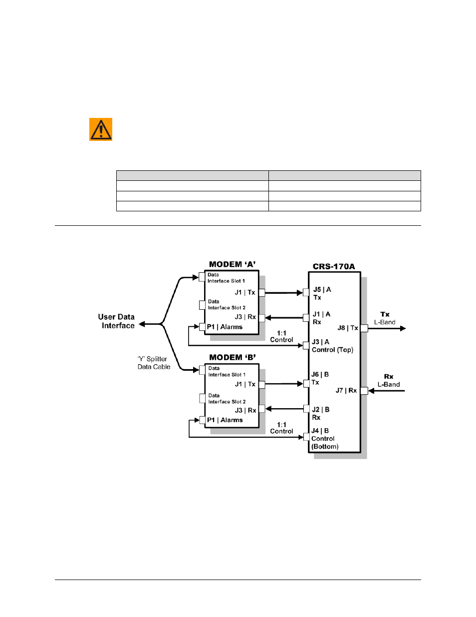
Figure 5-42. CDM-710GL Block Diagram – UserModemSwitchTraffic
Figure 5-42 shows the block diagram typical for the kits shown in Sects. 5.8.2.1.1 and Sect.
5.8.2.1.2. For example, Sect. 5.8.2.1.1 identifies the interface kit used with the CDI-10-1 Single
G.703 data interface.
With the exception of the CDI-70 Gigabit Ethernet data interface configuration shown in Sect.
5.8.2.2, which uses user-provided Ethernet cables and Layer 2 Switch, you must use one
interface kit per 1:1 modem pair for each interface (see examples for specific quantities).