Comtech EF Data CRS-170A User Manual
Page 28
CRS-170A L-Band 1:1 Redundancy Switch
MN/CRS170A.IOM
Introduction
Revision 13
1–8
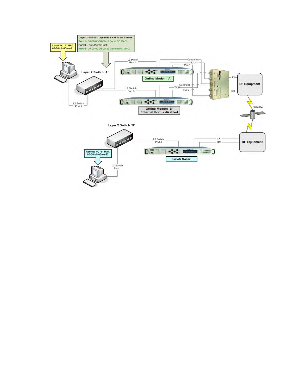
Figure 1-4. CDM-625/A, -850, -840, -760, -750, -710GL, -710, or -700 1:1 IP
Redundancy Managed Switch Mode
Figure 1-4 shows a Managed Switch Mode 1:1 IP Redundancy setup with the Ethernet data interface
of both modems connected to a Layer 2 Switch. Both modems are operational – Modem ‘A’ is Online
and connected to Port 4 of the Layer 2 Switch. Modem ‘B’ is Offline and connected to Port 3 of the
Layer 2 Switch, but the Ethernet link is not active because only the Online unit will have an active
Ethernet data interface. Also, Local PC ‘A’ is connected to Port 1 of the Layer 2 Switch.
When Ethernet traffic is sent from Local PC ‘A’ across the satellite link to remote PC ‘B’, the
Layer 2 Switch will “learn” the MAC addresses of both PCs and will have these dynamic entries in
its CAM Table:
Port 1 MAC 00-00-00-00-00-11 (Local PC ‘A’)
Port 3 No entries, port down
Port 4 MAC 00-00-00-00-00-22 (Remote PC ‘B’)