7 analog / digital operation, 8 multi-functional switch operation – Bronkhorst FLOW-SMS Series User Manual
Page 8
BRONKHORST HIGH-TECH B.V.
9.17.057
page 8
When connecting the system to other devices (e.g. to PLC), be sure that the integrity of the shielding is
not affected. Do not use unshielded wire terminals.
Operation via fieldbus is done by means of a flatconductor
cable connected with the main PC board.
Although all functionality is possible by means of RS232
and the switch on top of the instrument, it is important
that care should be taken when removing the upper part
of the housing.
In case that a shut‐off valve is mounted directly behind a control
module, please apply a right angled connector for Analog/RS232
communication.
2.7 Analog / Digital operation
2.7a Analog/Local operation
Connect the Mass Flow or Pressure Meter/Controller
to the power supply/readout unit using a cable with
9‐pin sub‐D connector.
EXAMPLE
Power:
+15...+24 Vdc
Analog input / output:
0…5Vdc / 0…10Vdc
0…20mA / 4…20mA
2.7b Digital/Fieldbus operation
For this procedure see description for RS232 or the applicable
fieldbus operation.
RS232 connection cable 7.03.366 enables to use (free)
Bronkhorst tooling programs for Windows
7.03.366
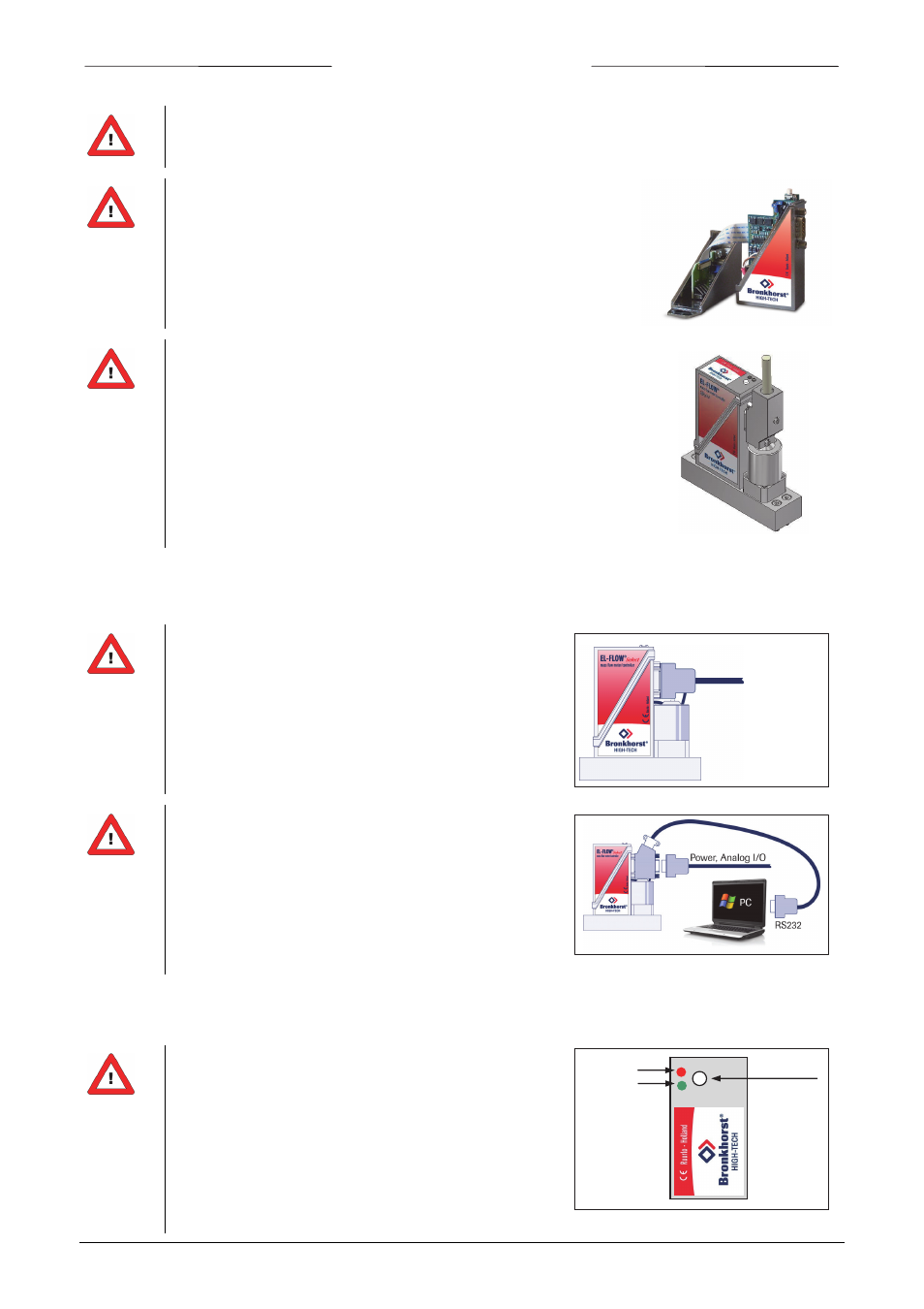
2.8 Multi-functional switch operation
Using the 2 colored LEDs and the switch on the instruments,
several actions can be monitored and started. The green LED
is used for status indication. The red LED is used for errors/
warnings/messages. The switch can be used to start several
actions, such as auto‐zero, restore factory settings and bus‐
initialization actions, if applicable.
See specific zero‐procedure below (10) for more details.
Error/warning LED
Status LED
Multifunctional
switch