Bronkhorst FLOW-SMS Series User Manual
Page 12
BRONKHORST HIGH-TECH B.V.
The control valve used in the FLOW‐SMS series is a standard, direct
operated solenoid valve (normally opened or normally closed),
operated through the PID‐control function on the pc‐board of the
flow or pressure meter. The diameter of the orifice under the
plunger is optimised for the customer’s specification.
9.17.057
page 12
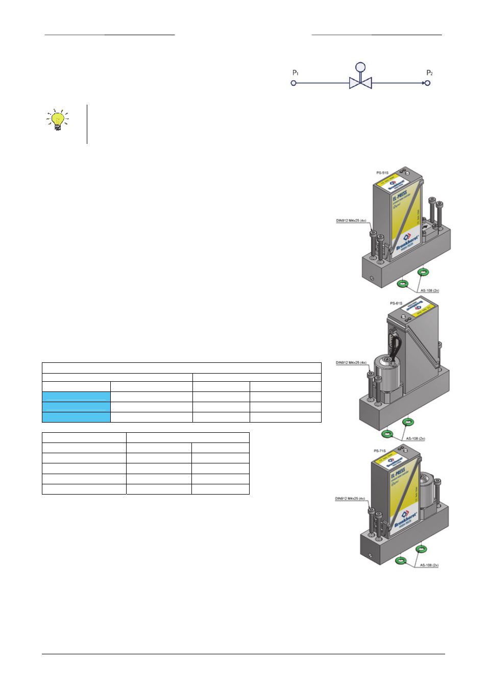
Instructions for replacing a Pressure Meter (PM) or
Pressure Controller (PC) module:
-
Removal
Ensure that the system is depressurised before taking
Pressure module apart.
The power must be off when removing the electrical connectors.
Loosen the 4 bolts with hexagon head counter clockwise to
release the Pressure module.
-
Replacement
Replace the gaskets 2xAS‐108, Viton, EPDM
or Kalrez.
All wetted parts have to be absolutely clean, don’t use oil or
grease and avoid dust!
Replace the Pressure module and tighten the M4 bolts with hexagon
head by turning clockwise, tighten crosswise with 2,0 Nm.
Replace the electrical connector.
Now the Pressure module has to be tested for leakage and
function.
Available Pressure Controller / Pressure Meter modules
Pressure Module
Description
Model number
Function
Smallest range
Highest range
PS‐502C
Meter
2..100 mbar
0,2…10 bar
PS‐602CV‐NC
Controller forward (NC)
5..100 mbar
0,5…10 bar
PS‐702CV‐NC
Controller back (NC)
20…100 mbar
2…10 bar
Pressure range (FS)
Indentification in model key
(bar)
Absolute
Relative
0,1 ‐ 0,35
350A
350R
0,35 ‐ 1,1
1k1A
1k1R
1,1 ‐ 6,0
6k0A
6k1R
6,0 – 21
21kA
21kR
Please keep in mind that the pressure rating for FLOW‐SMS is 10 bar only.
In pressure control systems the system widely determines the response behaviour of the control loop.
During testing the customer system is simulated as closely as possible. In some cases however
readjustment is needed for optimum performance under actual conditions.