4 install system, 5 leak check, 6 electrical connection – Bronkhorst FLOW-SMS Series User Manual
Page 7
BRONKHORST HIGH-TECH B.V.
2.4 Install system
9.17.057
page 7
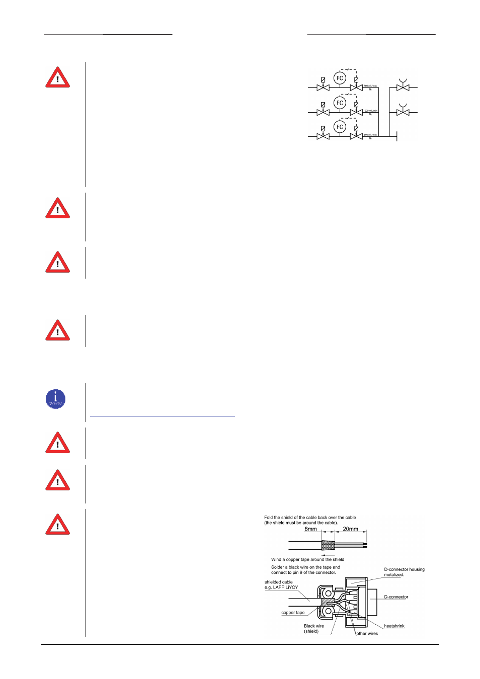
Install the FLOW‐SMS assembly in accordance with the
directions following the schematic diagram.
Tighten the fittings according to the instructions.
For compression type adapters, slide the nut and the ferrule
set in the right order at the tube. Insert the tubing fully into
the Adapter plate against the shoulder. Rotate the nut finger‐
tight, while holding the fitting body steady. Tighten the nut
three quarters clockwise for the fittings up to 4 mm and
3/16” tube OD. For larger fittings, tighten the nut one and one‐quarter.
For metal and o‐ring face seal type, rotate the nut finger‐tight, than turn the nut one‐quarter
clockwise, which is sufficient for the sealing. When the Adapter Plate is replaced the complete
module has to be tested for leakage and function.
The preferred mounting position of mass flow or pressure meters/controllers is horizontal. Other
mounting positions may introduce a zero shift and/or little gas and pressure dependency of the zero
signal. When mounting the assembly other than horizontal, zeroing of the instruments is advised. The
zeroing procedure is described in paragraph 2.10.
Avoid installation in close proximity of mechanic vibration and/or heat sources.
2.5 Leak check
Check the system for leaks before applying (fluid) pressure. Especially if toxic, explosive or other
dangerous fluids are used!
2.6 Electrical connection
Electrical connections must be made with standard cables or according to the applicable hook‐up
diagrams. These documents can be found at:
Please note that FLOW‐SMS instruments are rated IP40, implying that the electronics housings and
electrical connections do not offer any protection against moist environments.
The instruments contain electronic components that are susceptible to damage by electro static
discharge. Proper handling procedures must be taken during installation, removing and connecting the
electronics.
All instruments described in this manual carry
the CE‐mark and are complient with the EMC
requirements. However compliance with the
EMC requirements is not possible without the
use of proper cables and connector/gland
assemblies. For good results Bronkhorst High‐
Tech B.V. can provide standard cables.
Otherwise follow the guidelines as stated
hereby.