3 sas connector, Figure 3-11, Location of sas connector – Artesyn RTM-ATCA-7360 Installation and Use (June 2014) User Manual
Page 58: Figure 3-12, Sas connector pinout, Controls, leds, and connectors, Sas port activity leds
Controls, LEDs, and Connectors
RTM-ATCA-7360 Installation and Use (6806800J08M)
58
3.2.3.3
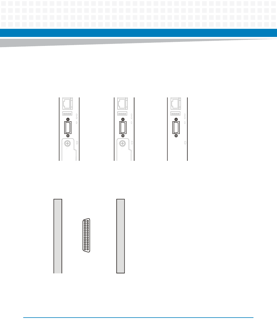
SAS Connector
The blade provides one SAS connector at its face plate. The location of the connector is shown
in the following figure.
The pinout of the serial interface connector is shown below.
Figure 3-11 Location of SAS Connector
Figure 3-12 SAS Connector Pinout
H
/
S
H
D
D
E
R
N
E
T
U
S
B
S
A
S
0
1
SAS port
activity LEDs
H
/
S
H
D
D
E
R
N
E
T
U
S
B
S
A
S
0
1
SAS port
activity LEDs
H
/
S
H
D
D
E
R
N
E
T
U
S
B
S
A
S
0
1
SAS port
activity LEDs
G1
S2
G2
S4
G3
S6
G4
S8
G5
S10
G6
S12
G7
S14
G8
S16
G9
G1
S1
G2
S3
G3
S5
G4
S7
G5
S9
G6
S11
G7
S13
G8
S15
G9
GND
Rx 0-
GND
Rx 1-
GND
RSVD
GND
RSVD
GND
RSVD
GND
RSVD
GND
Tx 1+
GND
Tx 0+
GND
GND
Rx 0+
GND
Rx 1+
GND
RSVD
GND
RSVD
GND
RSVD
GND
RSVD
GND
Tx 1-
GND
Tx 0-
GND
This manual is related to the following products:
See also other documents in the category Artesyn Equipment:
- ARTM-9405 16x10GbE Installation and Use Guide (May 2014) (64 pages)
- ATCA 7370 / ATCA 7370-S Installation and Use (January 2015) (256 pages)
- ATCA 7370 / ATCA 7370-S Installation and Use (September 2014) (254 pages)
- ARTM-831X Installation and Use (June 2014) (346 pages)
- ATCA-7350 - Integrating with Workbench User Guide (September 2014) (34 pages)
- ATCA-7350 Installation and Use (September 2014) (208 pages)
- ATCA-7365-CE Installation and Use (Jan 2015) (300 pages)
- ATCA-7365-CE Installation and Use (May 2014) (294 pages)
- ATCA-7365-CE Installation and Use (May 2014) (306 pages)
- ATCA-7368 Installation and Use (June 2014) (222 pages)
- ATCA-7475 Installation and Use (October 2014) (284 pages)
- ATCA-7480 Installation and Use (April 2015) (330 pages)
- ATCA-8330 Installation and Use (April 2015) (236 pages)
- ATCA-8320 Installation and Use (May 2014) (456 pages)
- ATCA-9305 User's Manual (May 2014) (270 pages)
- ATCA-9405 Installation and Use (October 2014) (168 pages)
- ATCA-F120 Installation and Use (August 2014) (122 pages)
- ATCA-F140 Installation and Use (September 2014) (138 pages)
- ATCA-MF106 Installation and Use (September 2014) (86 pages)
- Centellis-4440/AXP1440 Installation and Use (September 2014) (208 pages)
- Centellis 4410 (AXP-1410) Installation and Use (July 2014) (202 pages)
- Centellis 2100 Release 3.0 Installation and Use (March 2015) (192 pages)
- Centellis 2100 Release 3.0 Installation and Use (March 2015) (176 pages)
- Centellis 2000 User Card-10GE Installation and Use (May 2014) (54 pages)
- Centellis 2000 User Card-10GE with Telco Alarm Installation and Use (May 2014) (60 pages)
- COMX-CAR-210 Installation and Use (August 2014) (76 pages)
- COMX-P1022 Installation and Use (July 2014) (84 pages)
- COMX-P2020 Installation and Use (February 2015) (100 pages)
- COMX-CORE Series Installation and Use (August 2014) (128 pages)
- COMX-P2020 Installation and Use (July 2014) (100 pages)
- COMX-P4080-2G-ENP2 Installation and Use (August 2014) (70 pages)
- COMX-P4080 Installation and Use (August 2014) (126 pages)
- COMX-P40x0 ENP2 Installation and Use (August 2014) (130 pages)
- COMX-P40x0 ENP2 Installation and Use (January 2015) (140 pages)
- iVPX7225 RTM Installation and Use (April 2015) (56 pages)
- MITX-430/MITX-440-DVI-2E Installation and Use (August 2014) (118 pages)
- CPCI-6200 Installation and Use (May 2015) (234 pages)
- SCP-MITX-CORE-820-SM Installation and Use (August 2014) (132 pages)
- iVPX7225 Installation and Use (April 2015) (168 pages)
- MVME2502 Installation and Use (August 2014) (150 pages)
- MVME2502 Installation and Use (December 2014) (166 pages)
- MVME2500 VxWorks 6.8 AMP User Guide (August 2014) (40 pages)
- MVME2500 VxWorks 6.8 User Guide (April 2014) (44 pages)
- MVME3100 Single Board Computer Installation and Use (June 2014) (156 pages)
- MVME4100 Single Board Computer Installation and Use (June 2014) (136 pages)