Table 2-2, Critical temperature limits, Figure 2-1 – Artesyn RTM-ATCA-7360 Installation and Use (June 2014) User Manual
Page 34: Location of critical temperature spots (top side), Hardware preparation and installation
Hardware Preparation and Installation
RTM-ATCA-7360 Installation and Use (6806800J08M)
34
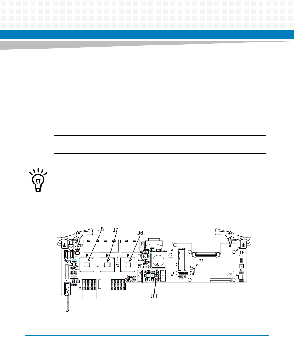
During the safety qualification of this product, the following on-board locations were
identified as critical with regards to the maximum temperature during blade operation. To
guarantee proper product operation and to ensure safety, you have to make sure that the
temperatures at the locations specified in the following are not exceeded. If not stated
otherwise, the temperature should be measured by placing a sensor exactly at the given
locations. For your convenience all temperature spots are shown in the figure below that
provides a detailed view of the product.
Table 2-2 Critical Temperature Limits
Location
Component
Temperature Limit
J6, J7, J8
Dual Ethernet Controller
70 °C
U1
SAS Controller
70 °C
Temperature limit is valid when measured on the component heat sink.
Figure 2-1
Location of Critical Temperature Spots (Top Side)