Programmer / calibration test, Programmer / create diagnostic report – Dataman 48Pro User Manual
Page 76
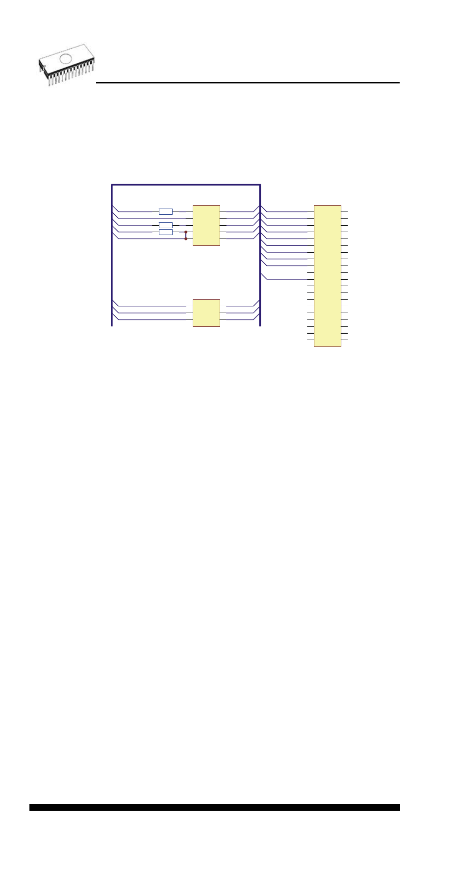
Diagnostic POD for ISP is available as optional accessory for
ISP-capable programmers. The order number: 70-0208
Schematic of Diagnostic POD for ISP connector (if you are in
hurry):
1
2
3
4
5
6
7
8
9
10
11
12
13
14
15
16
17
18
19
20 21
22
23
24
25
26
27
28
29
30
31
32
33
34
35
36
37
38
39
40
J1
DIP40 to ZIF socket
ZIF1
ZIF2
ZIF3
ZIF4
ZIF5
ZIF6
ZIF7
ZIF8
ZIF9
ZIF11
1
2
3
4
5
6
7
8
9
10
J2
HARTING 09185106324
1
2
3
4
5
6
J3
HARTING 09185066324
1
2
HR1A 47R
3
4
HR1B 47R
5
6
HR1C 47R
ZIF7
ZIF4
ZIF9
ZIF1
ZIF2
ZIF3
ZIF5
ZIF6
ZIF8
ZIF11
ZIF2
ZIF3
ZIF4
ZIF5
ZIF6
ZIF8
Sequence for testing 6 pins ISP connector:
1. Insert Diagnostic POD for ISP connectors into ZIF socket
of the programmer. Diagnostic POD must be inserted as
40 pins device.
2. Interconnect 6 pins connector of Diagnostic POD with an
ISP connector of the programmer with an ISP cable,
included in programmer delivery package. Be sure that
pins are interconnected properly (i.e. 1-1, 2-2, ..., 6-6).
3. Run selftest of ISP connector in PG4UW (Programmer /
Selftest ISP connector).
Sequence for testing 10 pins ISP connector:
1. Insert Diagnostic POD for ISP connectors into ZIF socket
of the programmer. Diagnostic POD must be inserted as
40 pins device.
2. Interconnect 10 pins connector of Diagnostic POD with
an ISP connector of the programmer with an ISP cable,
included in delivery programmer package. Be sure that
pins are interconnected properly (i.e. 1-1, 2-2, ..., 10-10).
3. Run selftest of ISP connector in PG4UW (Programmer /
Selftest ISP connector).
We recommend run this test every 6 months.
Programmer / Calibration test
Command executes test of programmer's calibration values.
Programmer / Create diagnostic report
Create Diagnostic report is used for writing more specific
diagnostic information to the Log window and consequently
76