Ethernet communication module dvpen01-sl – Delta Electronics Ethernet Communication Module DVPEN01-SL User Manual
Page 51
Ethernet Communication Module DVPEN01-SL
DVP-PLC Application Manual
49
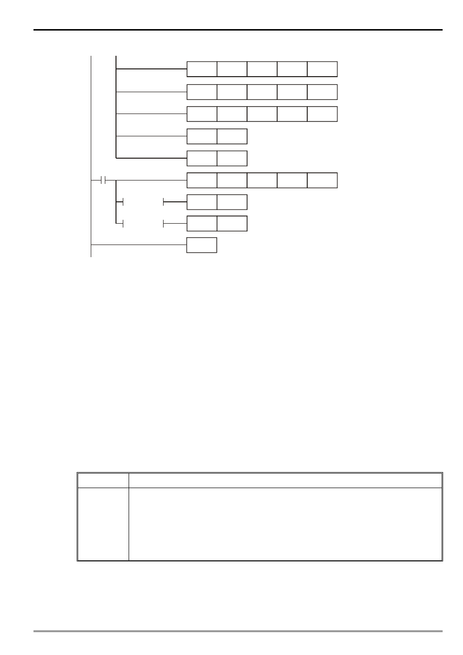
END
SET
M2
M1
RST
K100
K1
M2
K14
D14
RST
M2
RST
M2
= D14 K2
= D14 K3
FROM
K100
K1
TOP
K100
TOP
K1
K1
K0
K14
K13
K100
TOP
K1
K86
H1064
Explanations:
•
The data exchange will be executed every one second.
•
Write “0” into CR#28, and PLC_B will use CR#25 ~ CR#26 as the IP address of the destination
PLC.
•
Write the IP address of PLC_A into CR#25 and CR#26. The first two IP codes (192.168 =
H’C0A8) should be written into CR#26, and the last two IP codes (0.4 = H’0004) into CR#25.
•
Write the Modbus address of D0 (H’1000) in PLC_A into CR#81 and CR#84.
•
Write the Modbus address of D100 (register of RTC) (H’1064) into CR#86.
•
Write the number of registers K7 into CR#85.
•
Write “1” into CR#13 to start the data exchange.
•
CR#14 = 2 refers to successful execution. CR#14 = 3 refers to failed execution.
•
Once the data exchange is successful, the values in D1313 ~ D1318 in PLC_B will be written into
D0 ~ D6 of PLC_A.
6.12 Application of Modbus TCP Master (1)
Application
Compiling Modbus instrcution by PLC_B, making Y0 of PLC_A flashing
Network
requirement
(1) Adopting static IP.
(2) IP of PLC_A: 192.168.0.4
(3) IP of PLC_B: 192.168.0.5
(4) Update from PLC_B to PLC_A
(5) Use Modbus instrcution 050500FF00 to set “On” Y0.
(6) Use Modbus instrcution 0505000000 to set “Off” Y0.
(7) Y0 goes between On/Off once every one second.
1. See 6.1 for how to set up the communication.
2. Compile the ladder diagram in the MPU and download it to PLC_B. See below for the program design.
We do not need to write any corresponding ladder diagram into PLC_A.