Ethernet communication module dvpen01-sl – Delta Electronics Ethernet Communication Module DVPEN01-SL User Manual
Page 14
Ethernet Communication Module DVPEN01-SL
DVP-PLC Application Manual
12
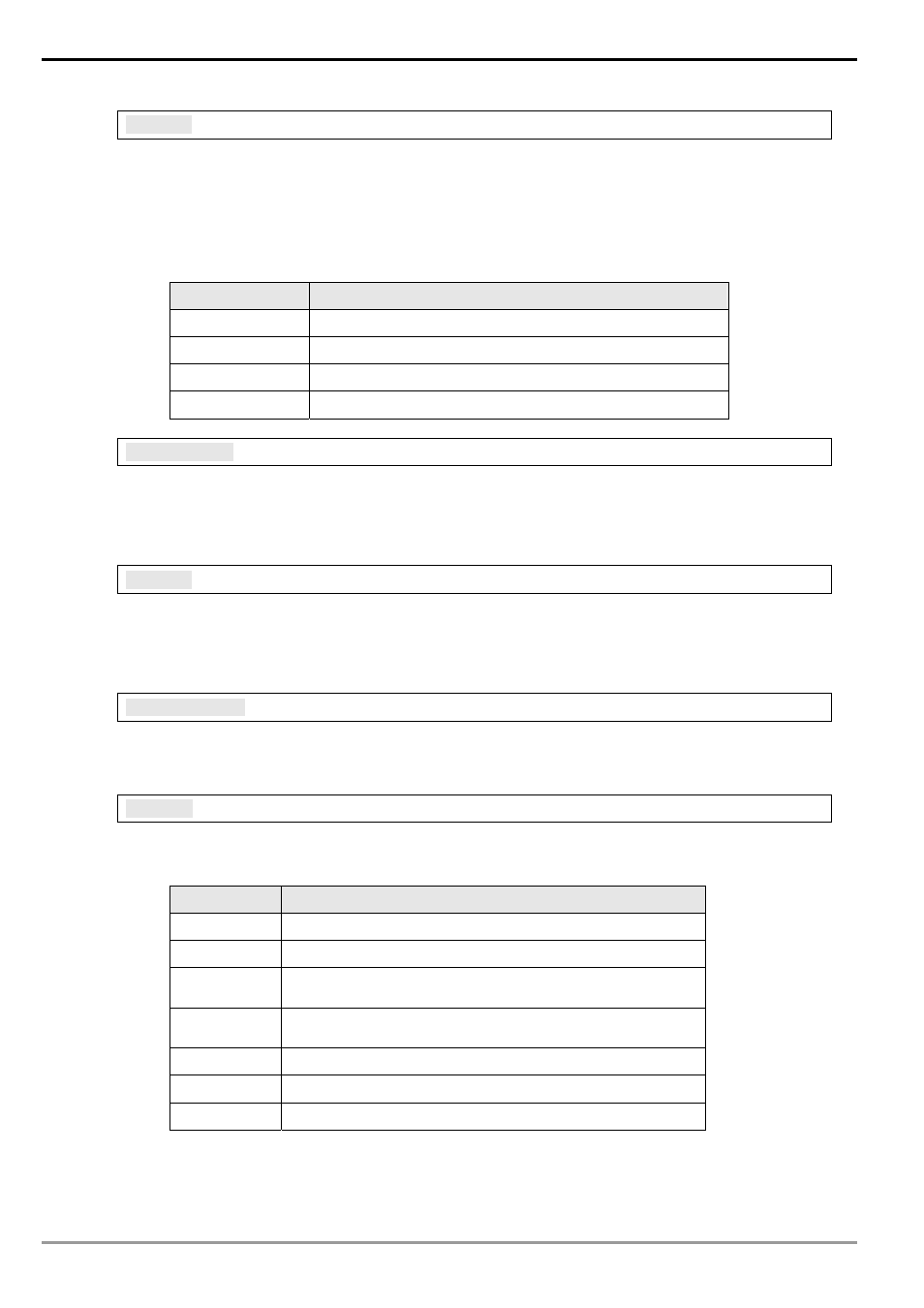
C R # 11 6 :
Modbus TCP Status
Explanations:
Displaying the current communication status of Modbus TCP mode. When the CR value is set
as”0” Æ the data have not yet been received; when the CR value is set as “1” Æ the data
exchange is in progress; when the CR value is set as “2” Æ the data exchange is successful;
when the CR value is set as “3” Æ the data exchange fails.
CR value
Data exchange status
0
The data have not been received.
1
The data exchange is in progress.
2
The data exchange is successful.
3
The data exchange fails.
C R # 11 7 , 11 8 :
Modbus TCP Destination IP
Explanations:
Setting up the destination IP address in Modbus TCP mode. See explanations on CR#70 and
#71 for how to set.
C R # 11 9 :
Modbus TCP Data Length
Explanations:
Setting up the length of communication data in Modbus TCP mode. Length for 8-bit mode: K1
~K100; length for 16-bit mode: K1 ~ K200.
C R # 1 2 0 ~ 2 1 9 :
Modbus TCP Data Buffer
Explanations:
Buffer for transmitted/received data in Modbus TCP mode.
C R # 2 5 1 :
Error Code
Explanations:
Table of error code:
Bit No.
Error
b0
The network is not yet connected.
b1
Incorrect IP setting
b2
CR#13 is set as “transmitting data”, but the data exchange
is forbidden.
b3
CR#13 is set as “transmitting data”, but the data exchange
mode has not yet been enabled.
b4 NTP-Server
connection
fails.
b7
SMTP-Server connection fails.
b8
DHCP has not obtained the correct network parameter.
4.3 Numbering of Left-Side Extension Modules
After DVPEN01-SL is installed properly, you need to compile the PLC program to control the extension
modules. PLC offers FROM instrcution (for reading) and TO instrcution (for writing) to control the control