Ethernet communication module dvpen01-sl – Delta Electronics Ethernet Communication Module DVPEN01-SL User Manual
Page 50
Ethernet Communication Module DVPEN01-SL
DVP-PLC Application Manual
48
Explanations:
•
The data exchange will be executed every one second.
•
Write “0” into CR#28, and PLC_B will use CR#25 ~ CR#26 as the IP address of the destination
PLC.
•
Write the IP address of PLC_A into CR#25 and CR#26. The first two IP codes (192.168 =
H’C0A8) should be written into CR#26, and the last two IP codes (0.4 = H’0004) into CR#25.
•
Write the data in RTC into CR#29 ~ CR#35.
•
Write “1” into CR#13 to start the data exchange.
•
CR#14 = 2 refers to successful execution. CR#14 = 3 refers to failed execution.
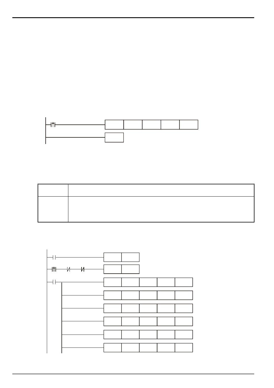
2. Compile the ladder diagram for PLC_A and download it to PLC_A.
END
M1013
K7
D0
K49
K100
FROM
Explanations:
•
The received data are stored in CR#49 ~ CR#55.
•
The data received every one second are written into D0 ~ D6.
6.11 Application of Data Exchange (3)
Application
Writing the time in RTC in PLC_B directly into D0 ~ D6 of PLC_A without writing in ladder
diagram into PLC_A.
Network
requirement
(1) Adopting static IP.
(2) IP of PLC_A: 192.168.0.4
(3) IP of PLC_B: 192.168.0.5
(4) Update from PLC_B to PLC_A.
1. See 6.1 for how to set up communication.
2. Compile the ladder diagram in the MPU and download it to PLC_B. We do not need to write any
corresponding ladder diagram into PLC_A.
M1013
K100
K1
K100
K100
K1
M2
M1
M1
SET
M1
TOP
K28
TOP
TOP
K100
TOP
K1
K0
K26
K25
H4
HC0A8
K1
K81
H1000
K100
K100
K1
TOP
TOP
K1
H1000
K84
K85
K7
D100
T D
R
M1000