Ethernet communication module dvpen01-sl, 10 application of data exchange (2) – Delta Electronics Ethernet Communication Module DVPEN01-SL User Manual
Page 49
Ethernet Communication Module DVPEN01-SL
DVP-PLC Application Manual
47
•
Write the data in RTC into CR#29 ~ CR#35.
•
Write “1” into CR#13 to start the data exchange.
•
CR#14 = 2 refers to successful exchange. CR#14 = 3 refers to failed exchange.
5. Compile the ladder diagram for PLC_A and download it to PLC_A.
END
M1013
K7
D0
K49
K100
FROM
Explanations:
•
The received data are stored in CR#49 ~ CR#55.
•
The data received every one second are written into D0 ~ D6.
6.10 Application of Data Exchange (2)
Application
Writing the time in RTC in PLC_B into D0 ~ D6 of PLC_A by designating IP by ladder
diagram.
Network
requirement
(1) Adopting static IP.
(2) IP of PLC_A: 192.168.0.4
(3) IP of PLC_B: 192.168.0.5
(4) Update from PLC_B to PLC_A
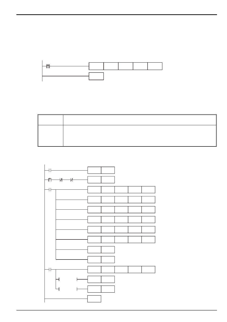
1. See 6.1 for how to set up the communication. Compile the ladder diagram in the MPU and download
it to PLC_B. See below for the program design:
END
M1013
K100
K1
K100
K100
K1
M2
M1
M1
SET
M1
TOP
K28
TOP
TOP
K100
TOP
SET
M2
M1
RST
K100
K1
M2
K14
D14
RST
M2
RST
M2
= D14 K2
= D14 K3
FROM
K1
K100
K1
TOP
K100
TOP
K1
K1
K0
K0
K26
K25
K29
K14
K13
D100
K7
H4
HC0A8
D100
T D
R
M1000