Ethernet communication module dvpen01-sl – Delta Electronics Ethernet Communication Module DVPEN01-SL User Manual
Page 47
Ethernet Communication Module DVPEN01-SL
DVP-PLC Application Manual
45
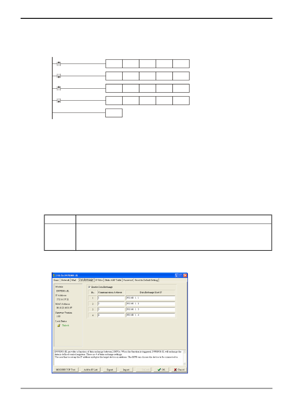
5. After all the settings in DVPEN01-SL are completed, compile the ladder diagram in the MPU and
download it to the MPU. See below for the program design:
END
X0
T0
K100
K3
K1
K4
K5
K6
K1
X0
T0
K100
K1
K1
T0
K100
K1
K1
T0
K100
K1
K1
Y0
Y0
Explanations:
•
If the rising-edge of X0 is triggered, X0 will go from Off to On. Write “1” into CR#3 of
DVPEN01-SL, and the first E-Mail will be sent out.
•
If the falling-edge of X0 is triggered, X0 will go from On to Off. Write “1” into CR#4 of
DVPEN01-SL, and the second E-Mail will be sent out.
•
If the rising-edge of Y0 is triggered, Y0 will go from Off to On. Write “1” into CR#5 of
DVPEN01-SL, and the third E-Mail will be sent out.
•
If the falling-edge of Y0 is triggered, Y0 will go from On to Off. Write “1” into CR#6 of
DVPEN01-SL, and the fourth E-Mail will be sent out.
6.9 Application of Data Exchange (1)
Application
Writing the time in RTC in PLC_B into D0 ~ D6 of PLC_A
Network
requirement
(1) Adopting static IP.
(2) IP of PLC_A: 192.168.0.4
(3) IP of PLC_B: 192.168.0.5”
(4) Update from PLC_B to PLC_A
1. See 6.1 for how to set up the communication.
2. Open the setup page of PLC_B and switch to “Data Exchange” page.