Rtx220 qr - manual, Introduction to iscsi, 5 installation steps – CRU RTX Secure 610-IR User Manual
Page 5: 1 what is iscsi, 2 what is the benefit of iscsi, 3 what is iscsi not, 1 hard drive installation
RTX220 QR - Manual
Page 5
RAID
Level
Description
Min.
Drives
Data
Redundancy
Data
Transfer
Rate
3
Also known as Bit-Interleaved Par-
ity. Data and parity information is
subdivided and distributed across
all disks. Parity must be equal to
the smallest disk capacity in the
array. Parity information normally
stored on a dedicated parity disk.
3
1 drive
Reads
are
similar to
RAID 0
5
Also known as Block-Interleaved
Distributed Parity. Data and par-
ity information is subdivided and
distributed across all disks. Can
withstand the failure of one drive.
The total capacity of all but one
of the drives is available for data
storage.
3
1 drive
Reads
are
similar to
RAID 0
6
Two parity bits are used to create
double redundancy. Can withstand
the failure of two drives. The to-
tal capacity of all but two of the
drives is available for data stor-
age.
4
2 drives
Slightly
less than
RAID 5
0+1
Also known as a mirror of striped
drives. Data and parity informa-
tion is subdivided and distributed
across all disks. Parity must be
equal to the smallest disk capac-
ity in the array. Parity information
normally stored on a dedicated
parity disk.
4
1 drives*
Transfer
rates are
similar to
RAID 0
10
Also known as a stripe of mirrors.
Data is striped across two sepa-
rate disks and mirrored to another
disk pair.
4
1 drives*
Transfer
rates are
similar to
RAID 0
30
Also known as a Striping Dedi-
cated Parity Array. RAID 30 breaks
up data into smaller blocks, and
then stripes the blocks of data to
each RAID 3 RAID set.
6
2 drives**
Transfer
rates are
similar to
RAID 0
50
RAID 50 combines the straight
block-level striping of RAID 0 with
the distributed parity of RAID 5
6
2 drives**
Transfer
rates are
similar to
RAID 0
60
RAID 60 combines the straight
block-level striping of RAID 0 with
the distributed double parity of
RAID 6
8
4 drives***
Transfer
rates are
similar to
RAID 0
JBOD
Just A Bunch of Disks. This is not
an actual RAID level because each
disk is treated as its own entity.
1
No data
protection
Very high
* One drive from each the RAID 0 and RAID 1 sets can fail without loss of data. If both
drives in either the RAID 0 or RAID 1 set fail, then the entire RAID will fail.
** One drive from each of the striped RAID sets could fail without loss of data. If two
drives in the same striped RAID set fail, then the entire RAID will fail.
*** Two disks from each of the RAID 6 sets could fail without loss of data. If three disks
in the same striped RAID 6 set fail, then the entire RAID will fail.
4. Introduction to iSCSI
4.1 What is iSCSI?
iSCSI is a technology that allows a data storage device to be
accessed over a TCP/IP network using SCSI protocols. When your
computer’s OS receives a request for data access, it generates a SCSI
command and then sends an IP packet across a network or direct
Ethernet connection. A software utility known as an iSCSI initiator is
used to generate the SCSI commands. Such a utility must be installed
on the computer before it can access an iSCSI storage device (See
Section 9 for installation instructions).
4.2 What is the Benefit of iSCSI?
An iSCSI storage device can be placed anywhere throughout a
network, so the device can reside at a great distance from the
computer which accesses it. It is also a very fast connection when
used on a gigabit network, achieving speeds of 100 megabytes (MB)/
sec or more. The connection it uses (RJ45—standard Ethernet port)
is commonly found on desktop and laptop computers, so there is no
need to purchase potentially expensive host bus adapters to provide
a connection.
4.3 What is iSCSI Not?
iSCSI storage devices are not Network Attached Storage (NAS)
devices. They have no built-in server capabilities and therefore
cannot be accessed by more than one computer at a time. Multiple
computers can only access the data if the iSCSI device is first
attached to a single computer which is then set up as a server.
5 Installation Steps
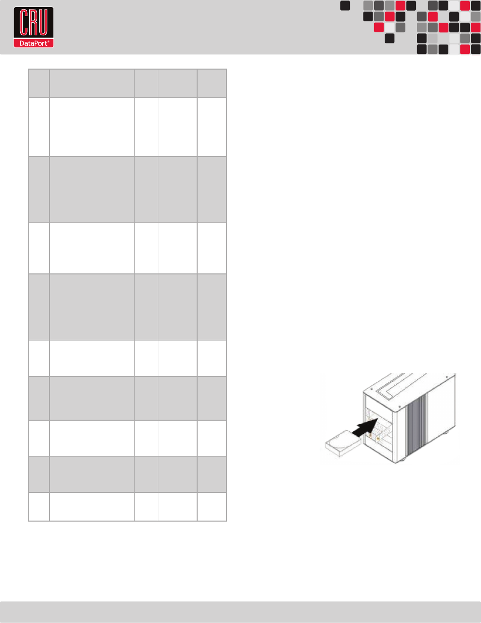
5.1 Hard Drive Installation
a. Pull the ejection
handle on the
TrayFree bay to
open the bay
door.
b. Insert a bare
SATA hard drive
into the bay.
Make sure it is
label-side up with the SATA connection on the drive inserted first.
c. Shut the bay door.
d. You can optionally secure each bay door by inserting an RTX Key
into its key lock and turning it 90 degrees clockwise. Locking the
bay doors is not necessary to operate the RTX Secure.
Sticker Card
Use the stickers on the provided sticker card to label each drive if you
plan to use Unique Encrypted Mode (see Section 5.2). This will prevent
the drives from getting mixed up when they are removed from the bays.