CRU DE50 IDE/PATA User Manual
De50 ide install guide, Rugged, reliable, mobile, secure, Removable ultra ata 100 drive enclosure
Rugged, Reliable, Mobile, Secure
TM
1-800-260-9800
www.CRU-DataPort.com
DE50 IDE Install Guide
Removable Ultra ATA 100 Drive Enclosure
NOTE: For Ultra ATA100 (100MByte/sec) operation, an Ultra ATA100 control-
ler and hard drive(s), and appropriate 40-pin, 80-conductor cable are required.
Drive Carrier Installation
1. Loosen and remove the four (4) M3 Phillips Flat Hd. screws located on
the sides of the drive carrier unit. Save these screws for Step 6.
2. Since the drive carrier unit is shipped pre-assembled, disassemble the
drive carrier unit into its three (3) main components (Figure 1).
3. Install the Drive Carrier Circuit Board (cable-side down) onto the drive
by attaching the I/O cable on the board to the drive.
4. Set Master/Slave drive designation. There are two ways to set the
Master/Slave drive designation for the DE50 unit, as described below.
NOTE: The information below is based on typical drive specifications.
Since specifications (specifically, pin assignments) between drive
manufacturers may vary, please refer to your drive manufacturer’s
documentation for information regarding Master/Slave configuration.
Cable Select Method (Recommended Method)
In most cases, there is no need to reconfigure the jumper on JMP1 located
on the rear of the drive carrier circuit board. A factory-installed jumper on
Pins B & D forces the drive into a Cable Select configuration (Figure 2).
With Cable Selection, the Master/Slave Drive designation is handled by
the Master/Slave Selection Jumper Option (J2) on the receiving frame
motherboard. If necessary, reconfigure jumper (factory-configured jumper
is for Master Drive designation). Skip section “Drive Select Method” and
continue with Step 5 of the Installation process.
Top
Cover
Drive Mounting
Bracket/Bottom
Plate Assembly
Drive Carrier
Circuit Board
Drive Select Method
In most cases, this method forces the drive into either a Master or Slave
Drive configuration. This method will override any configuration of the Mas-
ter/Slave Selection Jumper Option (J2) on the receiving frame motherboard.
The J2 jumper option is instead used to configure the unit ID display.
Master Drive
Remove the jumper from JMP1. Typically, no jumper installed on JMP1
forces the carrier into a Master Drive configuration (Figure 2).
Leave the J2 jumper option (on the receiving frame motherboard) as is for
Master Drive ID display purposes (factory-configured jumper is for Master
Drive designation).
Slave Drive
Install the jumper on JMP1 Pins C & D (Figure 2). Typically, a jumper
installed on Pins C & D forces the drive into a Slave Drive configuration
(refer to the drive manufacturer’s documentation for exact master/slave
jumper settings and reconfigure the jumper as necessary).
Configure the J2 jumper option for Slave Drive ID display purposes.
5. Carefully turn the drive/circuit board assembly upside-down (drive is
bottom-mounted into bracket). Install the drive mounting bracket and
secure with four (4) M3 screws (provided).
NOTE: Make sure that the drive circuit board is properly seated in
the mounting bracket slot before tightening screws.
6. Carefully insert the drive/bracket assembly into the top cover and
secure with the four (4) M3 screws (saved from Step 1).
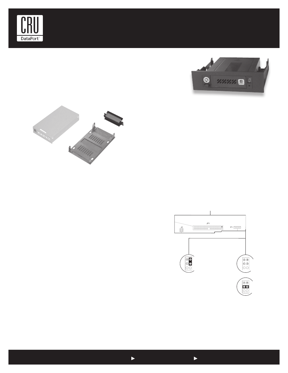
Figure 1: Drive Carrier Disassembly
Figure 2: Drive Carrier Circuit Board
I/O Connector
Recommended
Configuration
or
Typical Master Drive
Configuration
No Jumper
Installed
Typical Slave Drive
Configuration
Jumper Installed
on Pins C & D
Cable Select
Configuration
Jumper Installed
on Pins B & D
(Factory Default)