5 connection panel on the unit rear – BINDER UF V 500 User Manual
Page 26
UF V (E2+E2.1) 03/2013
page 26/112
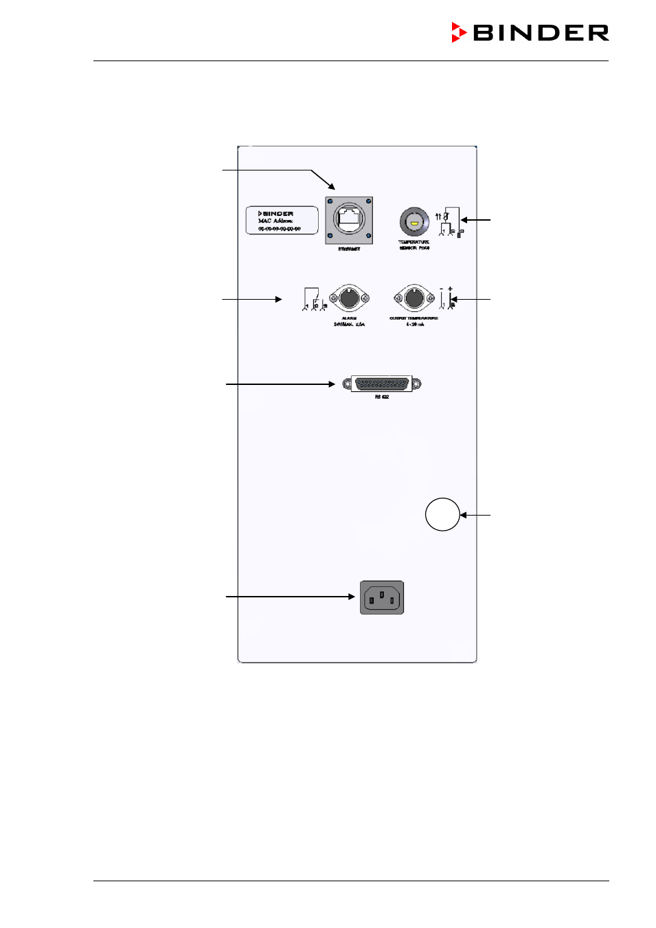
2.5 Connection panel on the unit rear
(7)
(8)
(9)
(10)
(11)
(12)
(13)
Figure 10: Rear connection panel of the freezer UF V (E2 / E2.1)
(7) Ethernet interface for computer communication (option, chap. 12.1)
(8) Connection socket for zero-voltage relay alarm contact (chap. 10.10)
(9) RS 422 interface for computer communication
(10) Connection socket for IEC connector cable with internal locking system
(44) Connection socket for additional Pt 100 temperature sensor (option, chap. 12.4)
(12) Connection socket for analog output 4-20 mA (chap. 12.3)
(13) Connection socket for the electrical connection of the CO
2
emergency cooling (option, chap. 11)
This manual is related to the following products: