Board jumpers, Board jumpers –12 – Altera Transceiver Signal Integrity Development Kit, Stratix IV GX Edition User Manual
Page 22
2–12
Chapter 2: Board Components
Configuration, Status, and Setup Elements
Transceiver Signal Integrity Development Kit,
November 2011
Altera Corporation
Stratix IV GX Edition Reference Manual
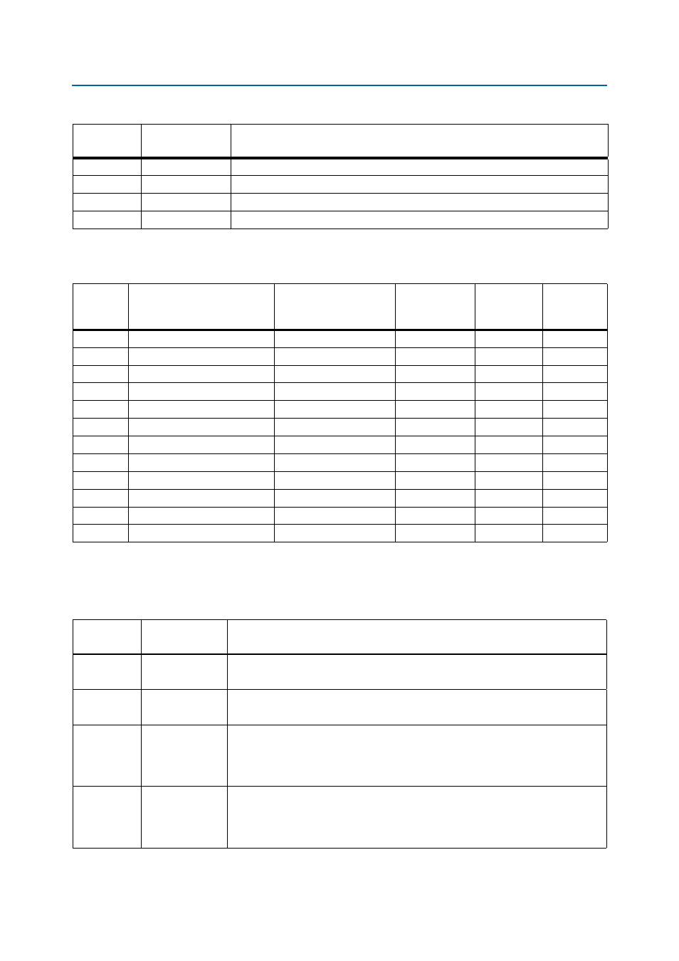
lists the surface mount LEDs which indicate the various status of the board.
Board Jumpers
lists the board jumper references, names, and functional descriptions.
D21
DUPLEX
Green LED. Illuminates to indicate Ethernet full duplex status.
D22
1000
Green LED. Illuminates to indicate Ethernet linked at 1000 Mbps.
D23
100
Green LED. Illuminates to indicate Ethernet linked at 100 Mbps.
D24
10
Green LED. Illuminates to indicate Ethernet linked at 10 Mbps.
Table 2–5. Board-Specific LEDs (Part 2 of 2)
Board
Reference
LED Name
Description
Table 2–6. Status LEDs
Board
Reference
Description
Schematic
Signal Name
I/O Standard
Stratix IV GX
Device
Pin Number
Other
Connections
D3
Power LED
5V
—
—
—
D17
FACTORY LED
FACTORY_IMAGE
2.5-V CMOS
—
U32 pin R8
D18
USER LED
USER_IMAGE
2.5-V CMOS
—
U32 pin R7
D16
ERROR LED
CONFIG_ERR
2.5-V CMOS
—
U32 pin R9
D19
Ethernet transmit activity LED
ENET_LED_TX
2.5-V CMOS
—
U40 pin 68
D20
Ethernet receive activity LED
ENET_LED_RX
2.5-V CMOS
—
U40 pin 69
D21
Ethernet Full-Duplex LED
ENET_LED_DUPLEX
2.5-V CMOS
—
U40 pin 70
D22
Ethernet 1000-Mbyte Link LED
ENET_LED_LINK1000
2.5-V CMOS
—
U40 pin 73
D23
Ethernet 100-Mbyte Link LED
ENET_LED_LINK100
2.5-V CMOS
—
U40 pin 74
D24
Ethernet 100-Mbyte Link LED
ENET_LED_LINK10
2.5-V CMOS
—
U40 pin 76
D6
Over-Temperature LED
FAN_LED
2.5-V CMOS
U33 pin F14
—
D7
USB-Blaster activity LED
USB_LED
3.3-V CMOS
—
U17 pin 8
Table 2–7. Board Jumpers (Part 1 of 2)
Board
Reference
Jumper Name
Description
J6
VCCA_SEL
When a jumper is installed on pins 1-2, VCCA is set to 2.5 V.
When a jumper is installed on pins 2-3, VCCA is set to 3.0 V
J11
VCCH_SEL
When a jumper is installed on pins 1-2, VCCH is set to 1.4 V.
When a jumper is installed on pins 2-3, VCCH is set to 1.5 V
J26
MAXII
BYPASS
When a jumper is installed, the MAX II CPLD device (U32) is included in the JTAG
programming chain.
When a jumper is removed, the MAX II CPLD device (U32) is removed from the JTAG
programming chain.
J62
PGMSEL
When a jumper is installed on pins 1-2, FPP configuration loads the user POF image
from flash.
When a jumper is installed on pins 2-3, FPP configuration loads the factory POF image
from flash.