Interconnect characteristics, Electrical measurement requirements, Symbol encoding – Altera SerialLite II Protocol User Manual
Page 16
16
Altera Corporation
SerialLite II Protocol Reference Manual
Physical Layer Description
Interconnect Characteristics
Refer to IEEE 802.3ae Clause 47.3.5 for XAUI characteristics and
OIF-CEI-02.0 Clause 6.A for CIE characteristics.
Electrical Measurement Requirements
Refer to IEEE 802.3ae Clause 47.4 for XAUI and OIF-CEI-02.0 Clause 2 for
CEI.
Symbol Encoding
The SerialLite II protocol encodes physical lanes using the
industry-standard 8B/10B encoding scheme. This approach takes 8-bit
data bytes and encodes them into 10-bit characters for transmission. The
10-bit coding is designed to allow the receiver to be able to recover a clock
signal from the transmitted data. Each 10-bit code has either an equal
number of ones and zeros (balanced) or the number of ones and zeros
differs by two (unbalanced). As the 10-bit code space is larger than the
8-bit data space, two 10-bit values can represent the same 8-bit code
where both 10-bit codes are either balanced or unbalanced. Unbalanced
pairs of 10-bit codes are compliments of each other to have the opposite
number of ones and zeros. Thus allowing the encoding to select between
unbalanced characters to evenly balance a stream of characters with a
maximum run length of five consecutive identical digits.
To maintain a balanced stream of characters, the encoder and decoder
keep a running disparity. Each 10-bit character of a specific code-group is
used for either positive running disparity (RD+) or negative running
disparity (RD-). The encoder selects between the two values based on the
current running disparity and ensures the maximum run length of five is
never violated. Running disparity is also used to detect if the 10-bit code
symbol has been corrupted.
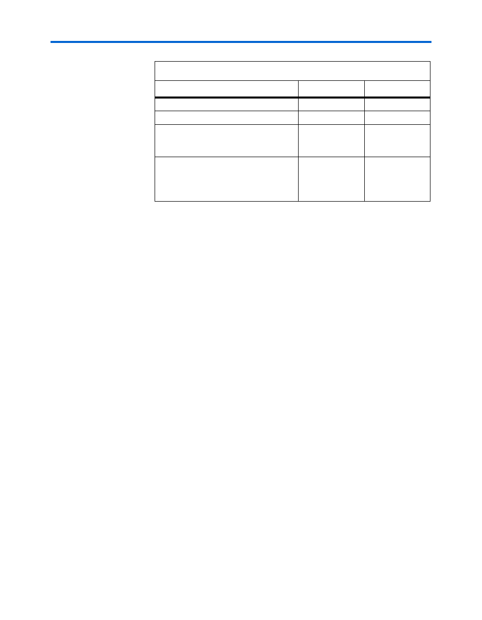
Bit Error Rate
10 –12
Differential Input Impedance
100 ± 10%
Ohm
Return loss
Differential
Common mode
10
6
dB
dB
Jitter amplitude tolerance
Minimum deterministic
Minimum deterministic plus random
Minimum total
0.37
0.55
0.65
UI
p - p
UI
p - p
UI
p - p
Table 2–3. Receiver Characteristics (Part 2 of 2)
Parameter
Value
Units