User leds (d9 through d16), Configuration dip switch (s6) – Altera Arria GX Development Board User Manual
Page 29
Altera Corporation
Reference Manual
2–19
October 2007
Arria GX Development Board
Board Components
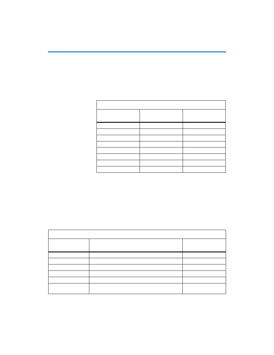
User LEDs (D9 Through D16)
The board provides eight user-defined LEDs. A logic 0 driven to an LED
turns it On; a logic 1 driven to an LED turns it Off.
Table 2–15
lists the schematic signal name and the corresponding
Arria GX device’s pin number.
Configuration DIP Switch (S6)
The configuration DIP switch is used to set up specific board functions,
such as FPGA bootstrap settings, configuration, or clock selection setup.
In the On position, the selected signal is driven to logic 0. In the Off
position, the selected signal is driven to a logic 1.
Table 2–16
shows the configuration DIP switch (S6) signal names and
descriptions.
Table 2–15. User-Defined LED Pin-Out
Board Reference
Schematic Signal Name
Arria GX Device
Pin Number
D9
USER_LED0
A12
D10
USER_LED1
A11
D11
USER_LED2
C13
D12
USER_LED3
B13
D13
USER_LED4
A13
D14
USER_LED5
B14
D15
USER_LED6
C14
D16
USER_LED7
C12
Table 2–16. Configuration DIP Switch Signal Name, Description, MAX II Device Pin Number (Part 1 of 2)
Schematic
Signal Name
Description
MAX II Device
Pin Number
CONFIG_MODE0
Configuration mode - bit 0
A1
CONFIG_MODE1
Configuration mode - bit 1
B2
DIPSW_PGM0
Configuration file page select - bit 0
C8
DIPSW_PGM1
Configuration file page select - bit 1
B9
DIPSW_PGM2
Configuration file page select - bit 2
A10
RUnLU
Remote/local configuration mode
Connected to
ACI6
of the
Arria GX device.