General user interfaces, Push button switches (s1, s2, s4), General user interfaces -17 – Altera Arria GX Development Board User Manual
Page 27: Push button switches (s1, s2, s4) -17
Altera Corporation
Reference Manual
2–17
October 2007
Arria GX Development Board
Board Components
General User
Interfaces
To allow you to fully leverage the I/O capabilities of the Arria GX device
for debugging, control, and monitoring purposes, the following general
user interfaces are available on the board:
■
Push buttons
■
User DIP switch
■
User LEDs
■
Board-specific DIP switch
■
Board-specific LEDs
■
Status LEDs
Push Button Switches (S1, S2, S4)
Board references S1, S2, and S4 are push-buttons allowing general user
I/O interfaces to the Arria GX device.
The push buttons connect directly to user I/O pins for user
programming. Although the USER_RESET push button’s purpose is
programming, its special label is intended to encourage its use as a logic
reset signal for FPGA designs so that user designs are reset in a consistent
manner.
1
All push buttons are a logic 1 until depressed.
Table 2–13
lists the board references, schematic signal names and
corresponding Arria GX pin numbers.
125 MHz oscillator (X2)
HSMA_REFCLK1_P
LVDS
J1
HSMA_REFCLK1_N
J2
Notes to
Table 2–12
:
(1)
Select between using the 100 MHz oscillator or the SM_CLK using CLK_SEL on the configuration DIP switch (S6).
Pin 7 in the 0n position selects SMA_CLK.
(2)
CLK2_P
and CLK2_N are connected to TP3 and TP4 respectively.
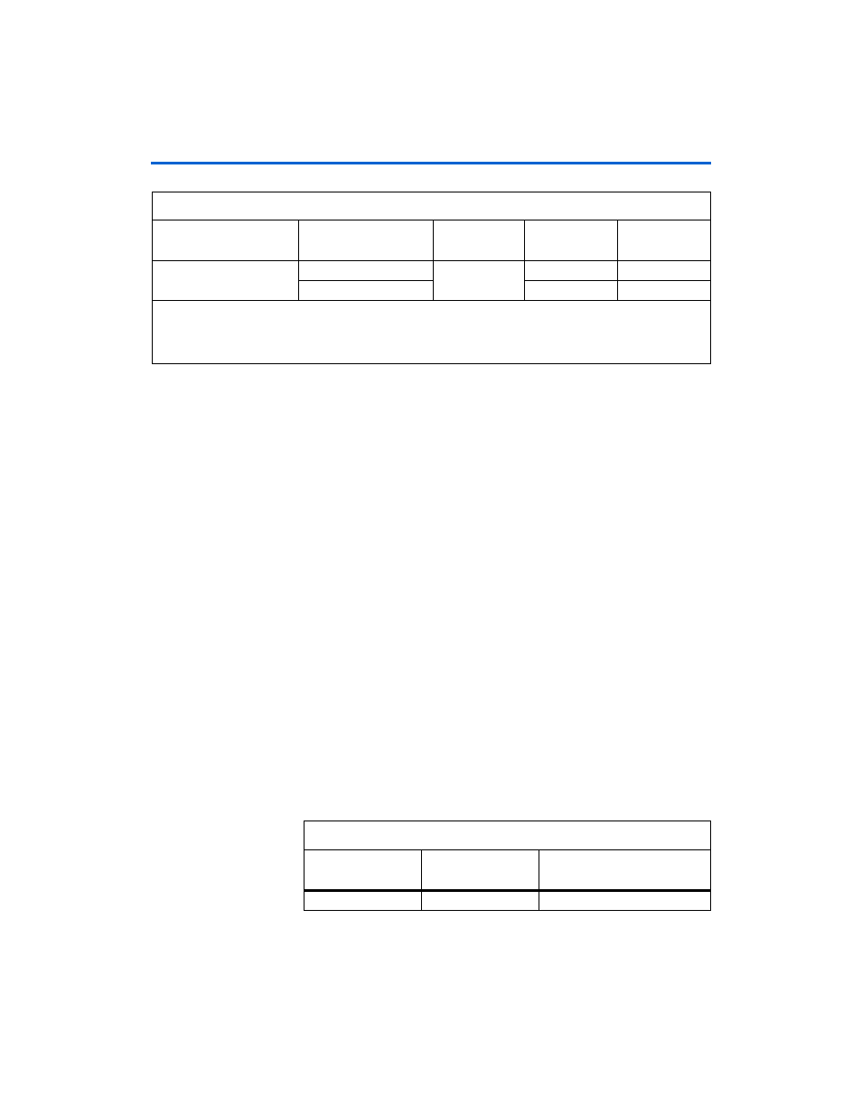
Table 2–12. Arria GX Development Board Clock Distribution (Part 2 of 2)
Source
Schematic
Signal Name
I/O Standard
Arria GX Pin
Number
MAX II Pin
Number
Table 2–13. Push-Button Switch Signal Names and Functions (Part 1 of 2)
Board Reference
Schematic
Signal Name
Arria GX Pin Number
S1
USER_PB0
A19