Setup elements, Board settings dip switch, Setup elements –19 – Altera DSP Development Kit, Stratix V Edition User Manual
Page 27: Board settings dip switch –19
Chapter 2: Board Components
2–19
Configuration, Status, and Setup Elements
July 2012
Altera Corporation
DSP Development Kit, Stratix V Edition
Reference Manual
lists the board-specific LEDs component references and manufacturing
information.
Setup Elements
The development board includes several different kinds of setup elements. This
section describes the following setup elements:
■
Board settings DIP switch
■
JTAG control DIP switch
■
PCI Express control DIP switch
■
MAX V reset push button
■
Program load push button
■
Program select push button
■
CPU reset push button
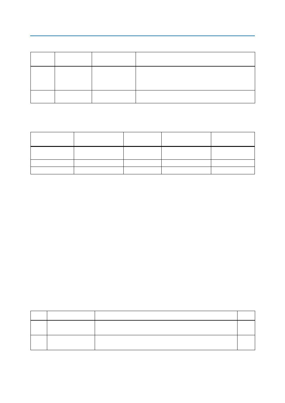
Board Settings DIP Switch
The board settings DIP switch (SW5) controls various features specific to the board
and the MAX V CPLD System Controller logic design.
lists the switch
controls and descriptions.
D4, D5, D6 PGM_LED
PGM_LED0
PGM_LED1
PGM_LED2
The sequence displayed determines if the factory design or a
user design is used to configure the FPGA from flash when you
press the PGM_LOAD push button. Refer to
for the
push button configuration settings.
D12
TEMP
OVERTEMPn
Red LED. Illuminates when a heat sink or fan should be installed.
Driven by the MAX1619 thermal sensor OVERTEMPn signal.
Table 2–10. Board-Specific LEDs (Part 2 of 2)
Board
Reference
LED Name
Schematic Signal
Name
Description
Table 2–11. Board-Specific LEDs Component References and Manufacturing Information
Board Reference
Description
Manufacturer
Manufacturer
Part Number
Manufacturer
Website
D1, D2, D4-D6, D15,
D17, D29-D32
Green LEDs
Lumex Inc.
SML-LX1206GC-TR
D16
Red LED
Lumex Inc.
SML-LX1206USBC-TR
D24
Blue LED
Lumex Inc.
SML-LX1206USBC-TR
Table 2–12. Board Settings DIP Switch Controls (Part 1 of 2)
Switch Schematic Signal Name
Description
Default
1
CLK_SEL
ON : SMA input clock select.
OFF : Programmable oscillator input clock select (default 100 MHz).
OFF
2
CLK_ENABLE
ON : On-Board oscillator enabled.
OFF : On-Board oscillator disabled.
ON