Altera HyperTransport MegaCore Function User Manual
Page 37
Chapter 3: Specifications
3–11
HyperTransport MegaCore Function Specification
© November 2009
Altera Corporation
HyperTransport MegaCore Function User Guide
Preliminary
For applications that require large bursts of data to be transmitted on one virtual
channel, the counter of that virtual channel can limit the throughput. This situation
occurs because when the counter reaches zero, no additional packets can be
transmitted in that virtual channel. If another virtual channel has no packets to be
transmitted, the link is idle until more credits are received. To maximize the
throughput in this type of application, you must prevent or minimize idle time on the
link by ensuring that new credits are received before the counter reaches zero. This
implementation ensures continuous transfer until all data is transmitted.
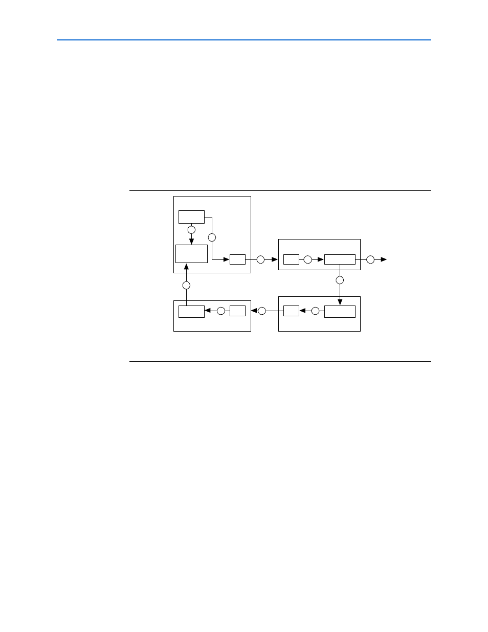
shows the components of the HT flow control loop for a single virtual
channel. The loop is from the time Transmitter A decrements its available Rx buffer
counter until the time that counter is incremented.
demonstrates the following flow:
1. Transmitter A schedules a packet for transmission and transfers it to the Tx FIFO
buffer. At the same time, the locally maintained available Rx buffer counter is
decremented.
2. The command is read out of the Tx FIFO buffer and transferred across the HT link
to receiver B’s Rx FIFO buffer.
3. The command is read out of the Rx FIFO buffer, decoded, and written into the Rx
buffer.
4. The user-side logic reads the command from the Rx buffer and frees the buffer. The
buffer free indication is transferred to the NOP generator in transmitter B.
5. The NOP containing the Rx buffer credit information is scheduled for transmission
and written into transmitter B’s Tx FIFO buffer.
6. The NOP is read out of transmitter B’s Tx FIFO buffer and transferred across the
HT link to receiver A’s Rx FIFO buffer.
7. The NOP is read out of receiver A’s Rx FIFO buffer and decoded.
Figure 3–8. HT Flow Control Loop
Note to
:
(1) Numbered steps are described in the following sections.
Transmitter A
Available Rx
Buffer
Counter
FIFO
Tx Buffer
Receiver A
NOP
Decoder
FIFO
Transmitter B
NOP
Generator
FIFO
Receiver B
Rx Buffer
FIFO
1
1
2
3
4
4
5
6
7
8