Shared rx/tx/ref clock – Altera HyperTransport MegaCore Function User Manual
Page 36
3–10
Chapter 3: Specifications
HyperTransport MegaCore Function Specification
HyperTransport MegaCore Function User Guide
© November 2009
Altera Corporation
Preliminary
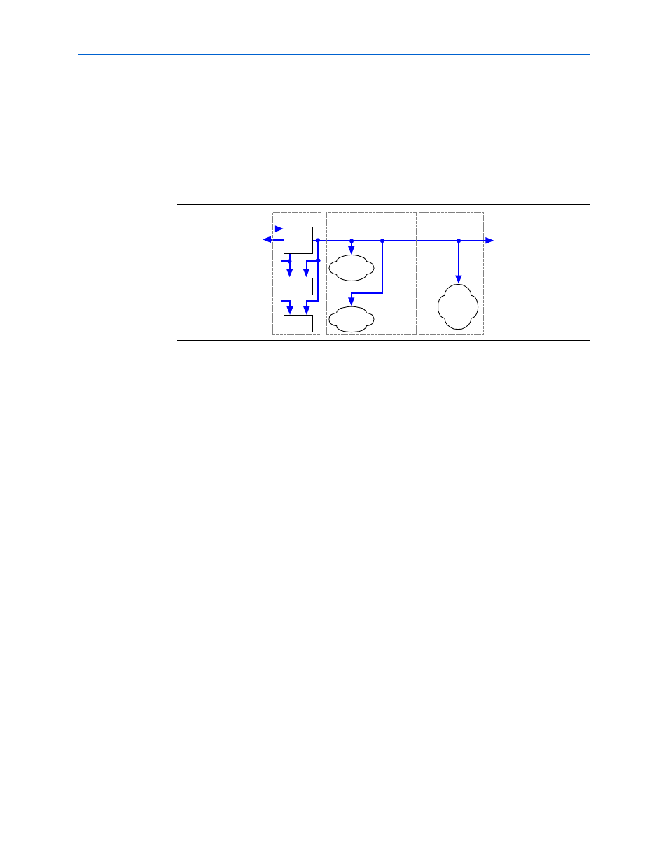
Shared Rx/Tx/Ref Clock
When you use the Shared Rx/Tx/Ref Clock option,
RxLnkClkD4
is used for the entire
HyperTransport MegaCore function and the local side interfaces. This
implementation provides the lowest latency MegaCore function variation and
typically results in the highest performance, and is a synchronous HT clock
implementation. All of the user logic that interfaces to the HyperTransport MegaCore
function must operate using
RxLnkClkD4
. This option is illustrated in
In this case, the Rx sync FIFO buffer and the Tx FIFO buffer are removed, yielding the
best throughput performance (i.e., the lowest latency through the MegaCore function
variation.)
1
You cannot use the
RefClk
input if you use the Shared Rx/Tx/Ref Clock option.
HyperTransport MegaCore Function Parameters and HT Link Performance
This section describes how the Rx buffer size parameters and clocking options of the
HyperTransport MegaCore function relate to throughput on the HT Link interface.
Refer to section 4.8 of the HyperTransport I/O Link Specification Revision 1.03 for
information about the flow control mechanism before reading this section.
The HT flow control mechanism is a credit-based scheme in which the transmitter
maintains a counter for each type of buffer in the receiver. When the link initializes,
the transmitter resets all of the counters to zero. When link initialization completes,
each receiver has its transmitter send buffer credits (transmitted within NOP
commands) for each type of buffer to indicate the number of buffers available for each
type of packet. When the transmitter transmits a packet of a particular type it
decrements that counter by one. The transmitter cannot transmit a packet if the count
for that type of packet is 0. After the receiver processes the packet and frees up the
buffer, it has its transmitter send a buffer credit for that type back to the original
transmitter.
The transmitter maintains six counters, one for each type of packet. If a command
packet has an associated data packet, the transmitter must ensure that it has credits
for both the control and data buffer types. Therefore, for most traffic on the HT link
interface, think of a pair of data and control counters as one. For simplicity, the rest of
this discussion refers to the control and data counters for each virtual channel as one
counter.
Figure 3–7. Shared Rx/Tx/Ref Clock Option
RxClk_i
Rx
Alignment
Logic
Tx
Alignment
Logic
Phy
Synch & Alignment
Protocol Interface
Protocol
Interface
Logic
Rx
SerDes
RxLnkClkD4
PLL
×
2
÷4
TxClk_o
Tx
SerDes
×
1