System block diagram, Introduction system block diagram – DMP Electronics Security Control Receiver SCS-1R User Manual
Page 8
SCS-1R Installation Guide
Digital Monitoring Products
3
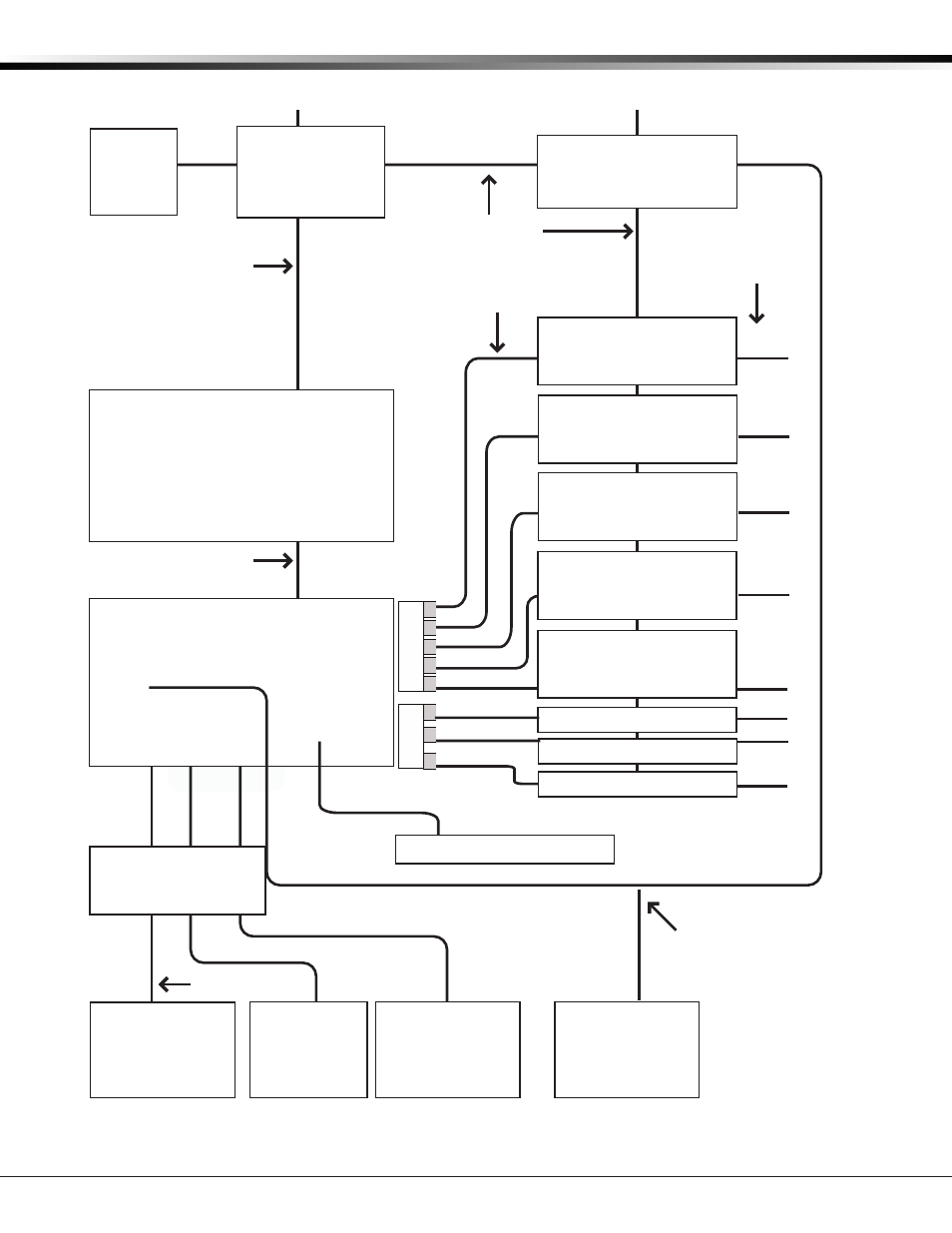
INTRODUCTION
System Block Diagram
Cooling
Fan
Model SCS-130
Transformer Card
120 VAC Input
Modem Rack
Backplane
Model SCS-208
Power Cable
Model SCS-120
Multibus Power
Supply Card
Multibus Backplane
Model SCS-204
Host Cable
J1
J2
J3
Listed Printer or
Listed Capture
Software
Card 1
Card 2
Card 3
Card 4
Card 5
Model SCS-110
Modem Rack
Supply Card
UPS Brownout Input
Model SCS-100 Line Card,
Model SCS-104 Line Card, or
Model SCS-101 Network
Interface Card
Automation
Computer
10-Conductor
Flat Cable
Model SCS-150
Receiver Processor
Board
RJ11X Cable or
Ethernet Cable
Membrane
Keypad and
32-Character LCD
3-connector
Ribbon Cable
J15
Keypad
Cable A3
Cable A1
Port
A3
Port
A1
J6 P
ort
Line Card Connector
1
2
3
4
5
Port
A2
Remote Link
for
Programming
Cable A2
Model SCS-203
Convenience Panel
Model SCS-100 Line Card,
Model SCS-104 Line Card, or
Model SCS-101 Network
Interface Card
Model SCS-100 Line Card,
Model SCS-104 Line Card, or
Model SCS-101 Network
Interface Card
Model SCS-100 Line Card,
Model SCS-104 Line Card, or
Model SCS-101 Network
Interface Card
Model SCS-100 Line Card,
Model SCS-104 Line Card, or
Model SCS-101 Network
Interface Card
Model SCS-104 Line Card
Model SCS-104 Line Card
Model SCS-104 Line Card
Line Card Connector
6
7
8
Card 6
Card 7
Card 8
J7
Po
rt
J3
Ethernet
Network Connection