3 evaluation by a control system, Evaluation by a control system – Pilz PIT m3.2p machine tools pictogram User Manual
Page 32
Function description
Operating Manual PIT m3.2p
1003176EN02
32
4.3.3
Evaluation by a control system
4.3.3.1
Evaluation of the Key ID number with transmittercontrolled communication
IDo0
(IDsync)
Bit 27
Bit 25
… Bit 16
Bit 15
Bit 14
IDo2
(IDout0)
Bit 26
[c]
[d]
t
en
IDo1
(IDclock)
[b]
max. 100 ms
Bit 13
Bit 11
… Bit 02
Bit 11
Bit 00
IDo3
(IDout1)
Bit 12
Bit 27
Bit 25
… Bit 16
Bit 15
Bit 14
IDi0
(IDin0)
Bit 26
Bit 13
Bit 11
… Bit 02
Bit 11
Bit 00
IDi1
(IDin1)
Bit 12
T
[a]
min. 60 ms
[f]
[e]
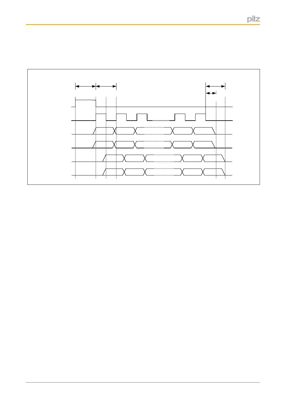
Fig.: Timing diagram for transmittercontrolled signal download
Legend:
The additional terminal designations (IDsync, IDclock, IDout0 etc.) are abbreviations for
the terminal signal's application.
IDo0
Control line
The signal is generated by the operating mode selector switch.
"0" signal
No transponder key is connected or the transponder key that
is connected is invalid.
"1" signal
A valid transponder key is created. The operating mode se
lector switch signals to the control system when the down
load starts. The signal is present for 100 ms.
IDo1
Test pulse line
The signal is generated by the operating mode selector switch and indic
ates the validity of the data bits at IDo2 and IDo3.
}
T = 100 ms
}
Duty cycle = 50%
IDo2, IDo3
Data lines for transmitting the Key ID number
The operating mode selector switch sends the Key ID number to the con
trol system via these two data lines.
IDo2:
Send Bit 27 … Bit 14
IDo3
Send Bit 13 … Bit 00
IDi0, IDi1
Data line for reading back the Key ID number
The control system sends the previously received Key ID number back to
the operating mode selector switch via these two data lines.
IDi0:
Receive Bit 27 … Bit 14
IDi1
Receive Bit 13 … Bit 00