2 operating mode interface, Operating mode interface – Pilz PIT m3.2p machine tools pictogram User Manual
Page 25
Function description
Operating Manual PIT m3.2p
1003176EN02
25
4.2
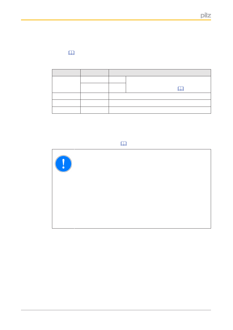
Operating mode interface
The operating mode interface consists of the monitored outputs SOM1 … SOM5 (see
). "SOM" stands for "Safe Operating Mode". The outputs are assigned to
buttons, which can be used to select an operating mode if they have the relevant authorisa
tion (transponder key):
Button
Output
Operating mode
1
SOM1
OM1
The operating mode OM1/OM5 is selected
based on the operating time of button 1 (see
Monitoring of operating time [
SOM5
OM5
2
SOM2
OM2
3
SOM3
OM3
4
SOM4
OM4
4.2.1
Switch behaviour after a transponder key is removed
If the transponder key is removed after changing to a different operating mode, it is possible
to configure the subsequent switch behaviour of SOM1 … SOM5. A DIP switch is available
).
NOTICE
Please note the following:
– The configuration may only be performed by a competent person.
– The configuration must be performed when the supply voltage is
switched off.
– The configuration is adopted as the device is started up, provided the
switch setting is valid. If not, the device switches to a "Device error"
fault condition.
– During operation, the DIP switch setting is monitored for any change.
If the switch setting is changed during operation, the device switches
to a "Device error" fault condition.