Pilz PSSu E F INC User Manual
Page 28
Wiring
Operating Manual PSSu E F INC(T)
1001454EN07
28
}
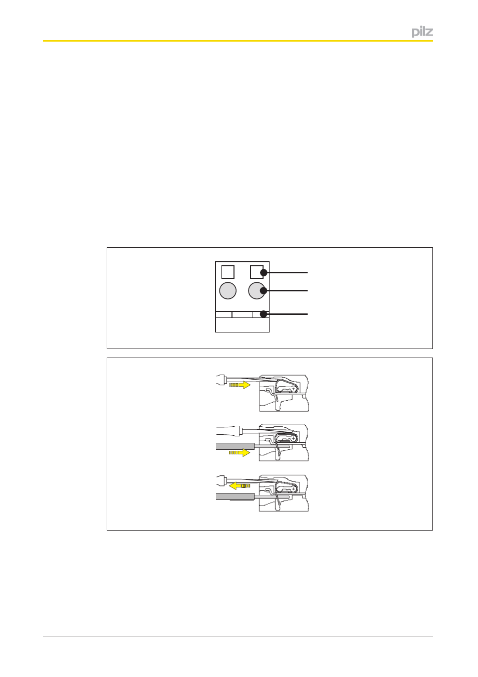
Strip the wire back 8 mm.
}
If necessary, label the connection level with a colour marker [3].
}
Base module with screw terminals:
–
Use a screwdriver to loosen the screw on the screw terminal [1]
–
Insert the stripped cable into the round fixing hole [2], as far as it will go.
–
Tighten up the screw on the screw terminal.
–
Check that the cable is firmly seated.
}
Base module with cage clamp terminals:
–
Insert the screwdriver [4] into the square hole [1].
–
Insert the stripped cable into the round fixing hole [2], as far as it will go [5].
–
Pull out the screwdriver [6].
–
Check that the cable is firmly seated.
21
11
[1]
[3]
[2]
[4]
[5]
[6]
Please note:
}
The minimum cable cross section for field connection terminals on the base modules is
0.14 mm
2
(AWG26).
}
The maximum cable cross section for field connection terminals is:
–
Digital inputs: 1.5 mm
2
(AWG16)
–
Digital outputs: 2.0 mm
2
(AWG14)