Pilz PNOZ m EF 2MM User Manual
Page 17
Commissioning
Operating Manual PNOZ m EF 2MM
1003107EN01
17
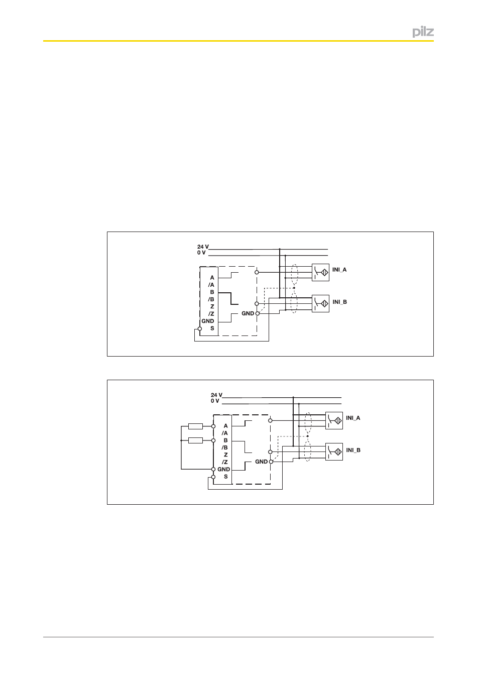
When connecting proximity switches please note:
}
Proximity switches can be connected to
–
terminals A12, B12, GND for axis 1 and A22, B22, GND for axis 2
or
–
tracks A, B and GND of the MiniIO socket (X12 for axis 1, X22 for axis 2).
}
Track S should be used to monitor the supply voltage (see drawing). A permitted
voltage range can be entered in the menu.
}
Connect the proximity switch to 24 VDC of the power supply.
}
When connecting the proximity switches, please refer to the chapter entitled "EMC
compliant wiring".
}
Invalid signals may occur with cable lengths >50 m. In this case we recommend that
you connect a resistor between the signal lines, as shown in the diagrams.
pnp proximity switch with resistor R = 10 kOhm
- PSEN in1p (16 pages)
- PSEN in1n (12 pages)
- PSEN rs2.0-300 (16 pages)
- PSEN rs1.0-175 (16 pages)
- PSEN enc m1 eCAM (46 pages)
- PSENme 1S / 1AS (16 pages)
- PSENme 1S / 1AS (6 pages)
- PSENme 2 / 2A (6 pages)
- PSENme 4 / 4A (5 pages)
- PNOZ m EF 2MM (6 pages)
- PNOZ m EF 2MM (6 pages)
- PSEN 1.1b-23/PSEN1.1-20/8mm/10m/EX/1unit (8 pages)
- PNOZ m EF 2MM (8 pages)
- PSEN 1.1p-20/PSEN 1.1-20/8mm/ 1unit (6 pages)
- PSEN 1.1p-29/PSEN 1.1-20/7mm/ix1/ 1unit (6 pages)
- PSEN 1.1b-25/PSEN1.1-20/8mm/10m/EX/1unit (8 pages)
- PSEN 1.1p-22/PSEN 1.1-20/8mm/ix1/ 1unit (6 pages)
- PSEN 1.1-10 / 1 actuator (6 pages)
- PSEN 1.2p-20/PSEN 1.2-20/8mm/ 1unit (6 pages)
- PSEN 1.1p-23/PSEN 1.1-20/8mm/ATEX/ 1unit (8 pages)
- PNOZ m EF 2MM (6 pages)
- PSEN 1.2p-22/PSEN 1.2-20/8mm/ix1/ 1unit (6 pages)
- PSEN 1.1p-25/PSEN 1.1-20/8mm/ATEX/ix1 (8 pages)
- PSEN 1.1-10 / 1 actuator (6 pages)
- PSEN 1.2p-23/PSEN 1.2-20/8mm/ATEX/ 1unit (8 pages)
- PSEN 1.1a-20/PSEN 1.1-20 /8mm/5m/1unit (6 pages)
- PSEN 1.2p-25/PSEN 1.2-20/8mm/ATEX/ix1 (8 pages)
- PSEN 1.1a-22/PSEN 1.1-20 /8mm/5m/ix1/1un (6 pages)
- PSEN ma1.3a-20/PSEN ma1.3-08/8mm/1unit (10 pages)
- PSEN ma1.3a-22/PSEN ma1.3-08/8mm/1unit (10 pages)
- PSEN ma1.3b-23/PSEN ma1.3-08/8mm/1unit (10 pages)
- PSEN ma1.3b-25/PSEN ma1.3-08/8mm/1unit (10 pages)
- PSEN ma1.3p-20/PSEN ma1.3-08/8mm/1unit (10 pages)
- PSEN ma1.3p-22/PSEN ma1.3-08/8mm/ix1/1un (10 pages)
- PSEN ma1.3n-20/PSEN ma1.3-08/8mm/1unit (12 pages)
- PSEN ma1.3-20 M12/8-0.15m 1switch (10 pages)
- PSEN ma1.4p-52/PSEN ma1.4-03mm/ 1unit (10 pages)
- PSEN ma1.4p-51/PSEN ma1.4-03mm/ 1unit (10 pages)
- PSEN ma1.4n-51/ 1switch (9 pages)
- PSEN ma1.4n-50/PSEN ma1.4-03mm/ 1unit (10 pages)
- PSEN ma1.4-51 M12/8-0.15m 1switch (10 pages)
- PSEN ma1.4p-57/PSEN ma1.4-10mm/ 1unit (10 pages)
- PSEN ma1.4a-52/PSEN ma1.4-03mm/ 1unit (10 pages)
- PSEN ma1.4a-51/PSEN ma1.4-10mm/ 1unit (10 pages)
- PSEN ma1.4p-50/PSEN ma1.4-03mm/ 1unit (10 pages)