6 commissioning, 1 wiring, 2 pin assignment of mini-io socket – Pilz PNOZ m EF 2MM User Manual
Page 16: 3 connection of proximity switches, Section 6, Commissioning, Wiring, Pin assignment of miniio socket, Connection of proximity switches, 6commissioning
Commissioning
Operating Manual PNOZ m EF 2MM
1003107EN01
16
6
Commissioning
6.1
Wiring
The wiring is defined in the circuit diagram of the PNOZmulti Configurator.
Please note:
}
Information given in the "Technical details" must be followed.
}
Use copper wire that can withstand 75°C.
}
The cable used to connect the rotary encoders and the proximity switches must be
shielded (see connection diagrams in the chapter entitled "EMCcompliant wiring").
}
The shield may only be connected to earth at a single point.
}
Earth loops should be avoided.
}
If possible, the connections for the various earth potentials ( ) should not be connected
on the PNOZ m EF 2MM but should be connected directly to the GNDs on the connec
ted units, otherwise noise susceptibility may be increased significantly (conductor loops
are not permitted).
CAUTION!
Only connect and disconnect the expansion module when the supply
voltage is switched off.
6.2
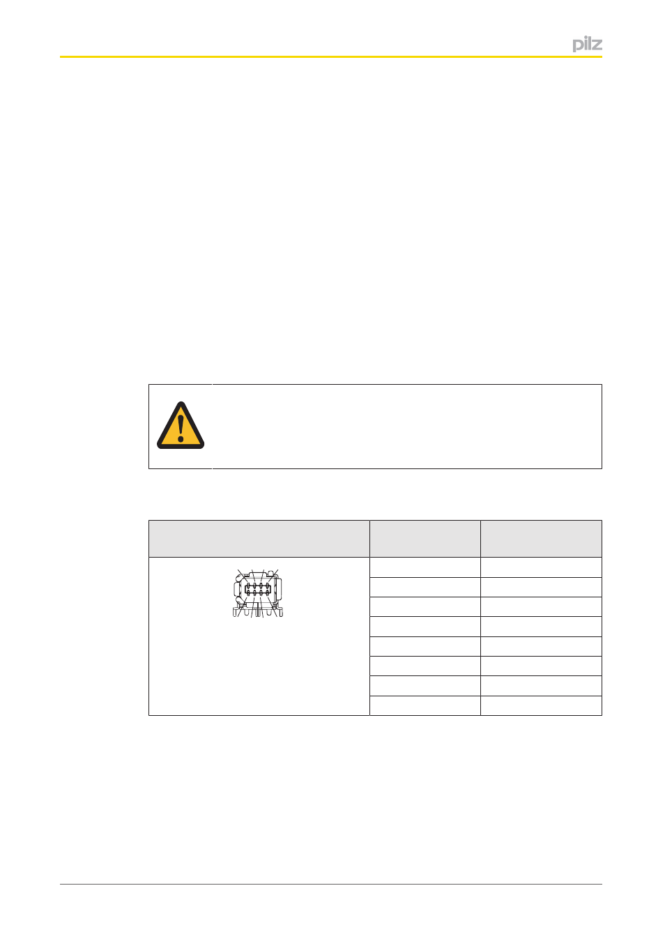
Pin assignment of MiniIO socket
MiniIO socket
8pin
PIN
Track
8 6 4 2
7 5 3 1
1
S
2
GND
3
Z
4
A
5
/A
6
/Z
7
B
8
/B
6.3
Connection of proximity switches
The following proximity switch combinations can be connected:
}
A: pnp, B: pnp
}
A: npn, B: npn
}
A: pnp, B: npn
}
A: npn, B: pnp