4 system reaction time, System reaction time – Pilz PNOZ m EF 2MM User Manual
Page 12
Function description
Operating Manual PNOZ m EF 2MM
1003107EN01
12
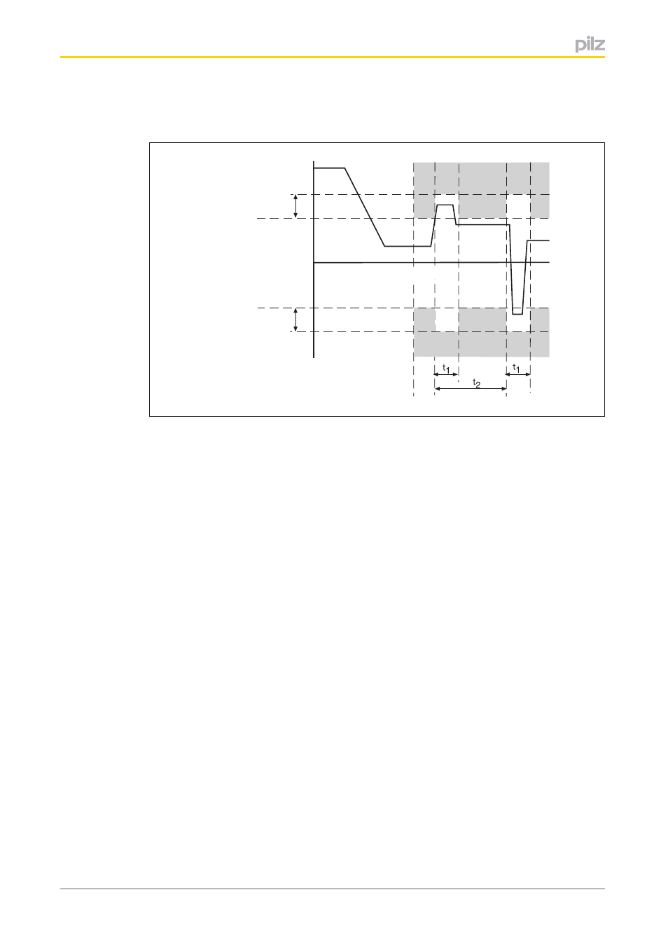
}
Tolerance amount as a %, which takes into account the size of the overshoots (max
imum permitted percentage by which the limit value may be exceeded)
Tolerance amount (%)
Limit
maximum speed
t
v
Limit
minimum speed
SSR-M
SSR-M
t
s
t
e
Tolerance amount (%)
Legend:
}
t
e
: Activation of the safety function SSRM
}
t
s
: Speed v exceeds the limit value and activates the tolerance range (tolerance time,
tolerance period, tolerance amount)
}
t
1
: Tolerance time
}
t
2
: Tolerance period
}
Tolerance amount (%): Tolerance amount of the two limit values, maximum and min
imum speed
Hysteresis
A hysteresis can be configured for the monitoring functions. This prevents the outputs from
bouncing if there are fluctuations around the response value. The hysteresis takes effect
when the output is switched on.
Standstill frequency
As implausible signals may arise due to edge jitter on the sensors around the standstill pos
ition, a standstill frequency must be configured in the PNOZmulti Configurator (edge jitter is
caused by the position control of the drive frequency converter or by external interference
signals).
If the value of the standstill frequency falls below the configured value, the feasibility check
of the sensors will no longer be run.
4.4
System reaction time
Calculation of the maximum reaction time between an input switching off and a linked out
put in the system switching off is described in the document "System Expansion".