4 error stack on the lc display, Error stack on the lc display – Pilz PNOZ m B0 User Manual
Page 29
Operation
Operating Manual PNOZ m B0
1002660EN03
29
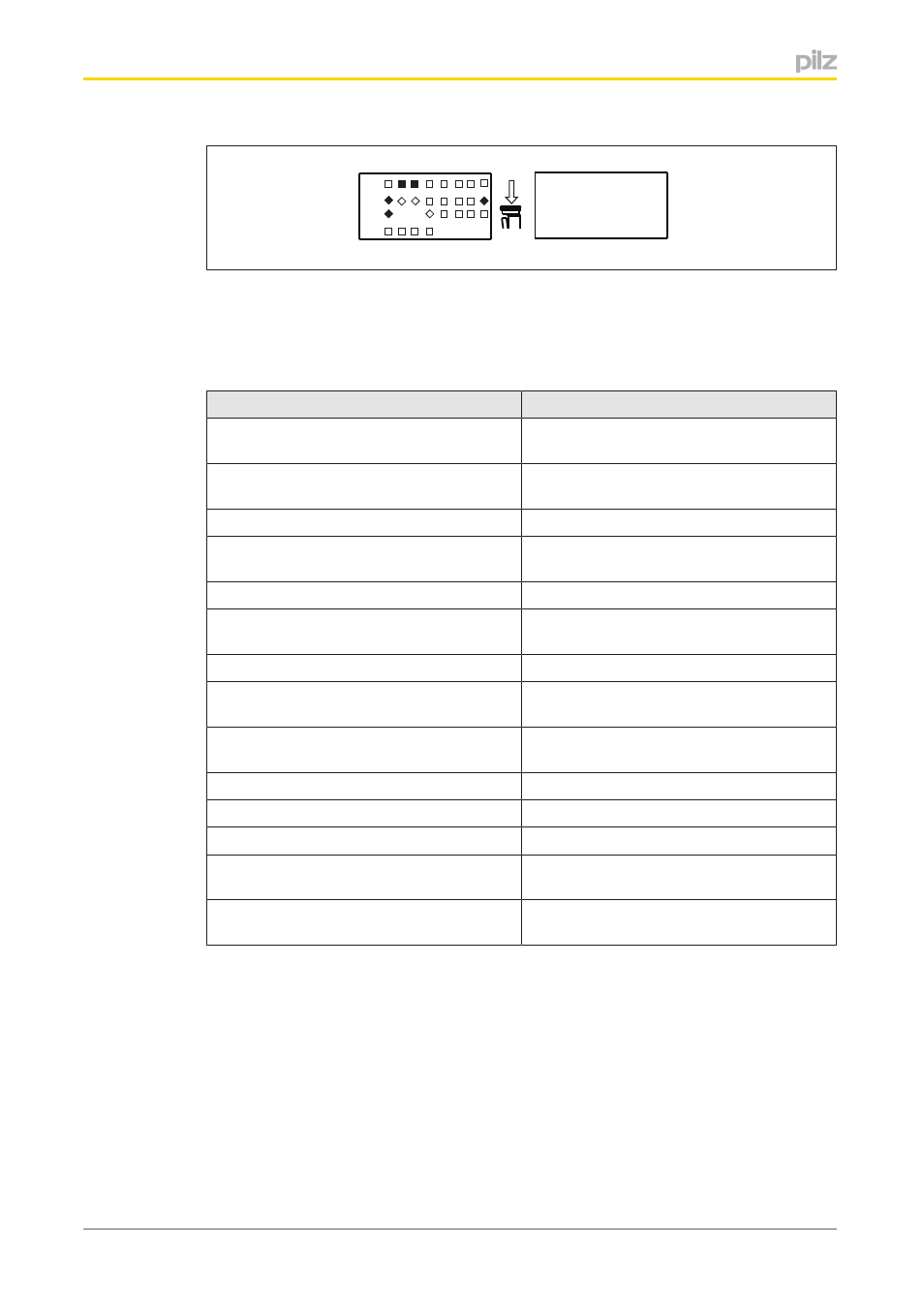
Output
faulty
*
X3
X1
X2
X4
T T
M
* If an error leads to a safe condition, the error message appears on the display immedi
ately. Once the cause has been rectified, you will need to reset the unit
Procedure for restarting the unit:
}
Press the rotary knob for between 3 and 8 seconds to reset the unit.
Error messages
Error
FAULTY PROJECT
Chip card contains a project which is faulty
or incompatible.
CHIP CARD ?
Chip card is not inserted, blank or unread
able
FAULTY TEST PULSE
Error caused by test pulse
PARTIALLY OPERATED
Function element was or is partially oper
ated
FEED BACK LOOP
Exernal error at the feedback loop inputs
OPERATING MODE SWITCH SELECTOR
Error on the operating mode selector switch
function element
FAULTY OUTPUT
External error on the output
OUTPUT WITH ADVANCED FAULT
DETECTION
External error on the output with advanced
fault detection
LOAD SUPPLY
Error in the supply voltage for the semicon
ductor outputs
FAULTY DEVICE
Internal error on the base unit
SUPPLY LOW
Supply voltage is below the tolerance level
SUPPLY HIGH
Supply voltage exceeds the tolerance level
CONFIGURATION
Hardware registry does not match the con
figuration
TEMPERATURE
Operating temperature is outside the permit
ted range
7.2.4
Error stack on the LC display
The error stack can be read from the PNOZmulti Configurator or shown on the LC display.
The error stack helps Pilz technical support with fault diagnostics. The error stack can store
up to 64 status and error messages.
The following information is shown on the LC display:
}
Sequential number of an error stack entry. A new error stack entry is stored in first
place.
}
Error class (EC) and error information (EI)