5 installation, 1 install base unit without expansion module, 2 control cabinet installation – Pilz PNOZ m B0 User Manual
Page 14: Section 5, Installation, Install base unit without expansion module, Control cabinet installation, 5installation
Installation
Operating Manual PNOZ m B0
1002660EN03
14
5
Installation
5.1
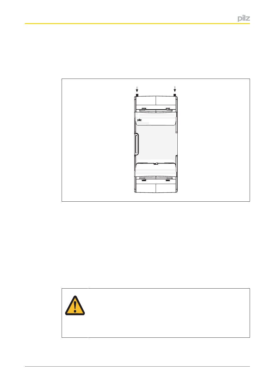
Install base unit without expansion module
Make sure that the terminators are inserted on the top left and right of the unit.
IM0 IM1 IM2
I6
I5
I4
IM3
I7
I8
I9
I10
I14
I13
I12
I11
I15
X3
X1
X4
X2
PNOZ mm0.1p
T0
T1
T2
O2
O1
O0
T3
O3
IM16 IM17 IM18
0 V
A2
A1
IM19
24 V
M20
M21
M22
M23
5.2
Control cabinet installation
}
The unit should be installed in a control cabinet with a protection type of at least IP54.
}
Fit the safety system to a horizontal mounting rail. The venting slots must face upward
and downward. Other mounting positions could damage the safety system.
}
Use the locking elements on the rear of the unit to attach it to a mounting rail.
}
In environments exposed to heavy vibration, the unit should be secured using a fixing
element (e.g. retaining bracket or end angle).
}
Open the locking slide before lifting the unit from the mounting rail.
}
To comply with EMC requirements, the mounting rail must have a low impedance con
nection to the control cabinet housing.
CAUTION!
Damage due to electrostatic discharge!
Electrostatic discharge can damage components. Ensure against discharge
before touching the product, e.g. by touching an earthed, conductive sur
face or by wearing an earthed armband.