4function description, 1 device properties – Pilz PNOZ mml1p User Manual
Page 17
Pilz GmbH & Co. KG, Felix-Wankel-Straße 2, 73760 Ostfildern, Germany
Telephone: +49 711 3409-0, Telefax: +49 711 3409-133, E-Mail: [email protected]
4-3
4.1
Device properties
4
Function Description
Input delay and switch-off delay are only included once in the reaction
time. The data transmission time between the link modules is multi-
plied by the number of connections.
Please refer to the connection examples under "Preparing for opera-
tion".
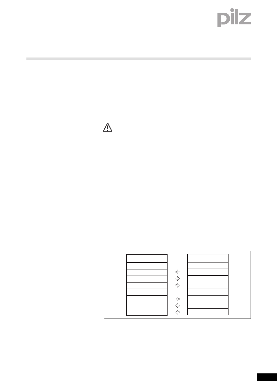
Virtual inputs and outputs:
Inputs and outputs for both PNOZmulti systems are assigned in the
PNOZmulti Configurator. Inputs and outputs with the same number are
assigned to each other, e.g. output o5 on one PNOZmulti system to in-
put i5 on the other PNOZmulti system.
Funktionen_multi_Verbindungsmodul_l1p_Bild
CAUTION!
For signals that are forwarded or received via the link module,
the overall reaction time, e.g. the maximum reaction time of the
series connection of n base units, must always be considered in
the risk assessment.
The risk assessment must consider all hazards as regards the
reaction time and the safety distance. The overall reaction time
must not delay the arrival of a safe condition by more than the
permitted time.
Base unit 1
Virtual outputs
o0
...
o31
Virtual inputs
i0
...
i31
Base unit 2
Virtual inputs
i0
...
i31
Virtual outputs
o0
...
o31