Pilz PNOZ p1vp 30s User Manual
Page 6
- 6 -
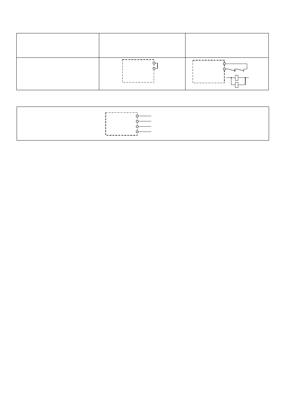
Eingangskreis
Input circuit
Circuit d’entrée
Not-Halt/E-STOP/Arrêt d’urgence
Schutztür/Safety gate/Protecteur mobile
Automatischer Start ohne Rückführkreis
Automatic reset without feedback loop
Réarmement automatique sans boucle de
retour
Automatischer Start mit Rückführkreis
Automatic reset with feedback loop
Réarmement automatique avec boucle de
retour
Y1
Y2
K5 K6
Y1
Y2
K5
K6
Y30
Y31
24 V DC
SPS/PLC/API
0 V
Y32
Y35
SPS/PLC/API
• Connect the feedback loop (jumpers or
external contactors) in series to the reset
circuit.
• Connect the semiconductor outputs.
• Set the delay-on de-energisation.
- Set fixed times on the rotary switch:
depending on the unit type 0, 5, 10, 15,
20, 25 s or 0, 50, 100, 150, 200, 250 s
- Set intermediate values via the
potentiometer:
depending on the unit type 0.3 - 5 s or
1.5 - 50 s.
Operation
Status indicators:
• "CH.1 IN", "CH.2 IN" and "OUT" illumi-
nate: the output signal is active on the
PNOZpower bus
• "CH.1 IN", "CH.2 IN" and "OUT" go out:
the output signal is not active on the
PNOZpower bus
• When the starter button is pressed, the
"START" LED will illuminate. The unit is
only ready for operation when the starter
button is released. The "START" LED is
no longer illuminated.
Reactivation:
• Close the input circuit, or operate the
start button only when the delay time +
tolerance have elapsed.
Fault indicator:
• The "FAULT" LED illuminates, the "PWR"
LED does not illuminate, the semiconduc-
tor Y35 is disabled: Earth faults or short
cirucuits in the PNOZ p1vp: An electronic
fuse causes the output contacts of the
expansion modules to open. Once the
cause of the fault has been removed and
operating voltage is switched off, the unit
will be ready for operation after
approximately 1 minute.
• The "FAULT" LED does not illuminate,
the "PWR" LED illuminates, the semicon-
ductor Y35 is disabled: Expansion units
faults (collective fault message)
• The "PWR" LED is not illuminated if short-
circuit or the supply voltage is lost.
On the next two pages you will find the
terminal configuration and the dimensions of
the unit.
• Schließen Sie den Rückführkreis
(Brücke oder externe Schütze) in Reihe
zum Startkreis an.
• Schließen Sie die Halbleiterausgänge
an.
• Stellen Sie die Rückfallverzögerung ein.
- Am Drehschalter feste Zeiten einstellen:
je nach Gerätetyp 0, 5, 10, 15, 20, 25 s
oder 0, 50, 100, 150, 200, 250 s
- Mit dem Potenziometer Zwischenwerte
einstellen:
je nach Gerätetyp 0,3 - 5 s oder
1,5 -50 s.
Betrieb
Statusanzeigen:
• "CH.1 IN", "CH.2 IN" und "OUT" leuchten:
das Ausgangssignal auf dem
PNOZpower-Bus ist aktiv
• "CH.1 IN", "CH.2 IN" und "OUT" erlö-
schen: das Ausgangssignal auf dem
PNOZpower-Bus ist nicht aktiv
• Bei Betätigen des Starttasters leuchtet die
LED "START". Erst nach Loslassen des
Starttasters ist das Gerät betriebsbereit.
Die LED "START" leuchtet nicht mehr.
Wieder aktivieren:
• Schließen Sie den Eingangskreis oder
betätigen Sie den Starttaster erst
wieder nach Ablauf der Verzögerungs-
zeit + Toleranz.
Fehleranzeige:
• LED "FAULT" leuchtet, die LED "PWR"
leuchtet nicht, der Halbleiterausgang Y35
sperrt: Erd- oder Querschluss bei PNOZ
p1vp: Eine elektronische Sicherung
bewirkt das Öffnen der Ausgangskontakte
der Erweiterungsmodule. Nach Wegfall
der Störungsursache und Abschalten der
Betriebsspannung für ca. 1 Minute ist das
Gerät wieder betriebsbereit.
• LED "FAULT" leuchtet nicht, die LED
"PWR" leuchtet, Halbleiterausgang Y35
sperrt: Fehler an Erweiterungsgeräten
(Sammelstörmeldung)
• LED "PWR" leuchtet nicht: Kurzschluss
oder Versorgungsspannung fehlt
Auf den beiden letzten Seiten finden Sie die
Klemmenbelegung und die Abmessungen
des Geräts.
• Raccordez la boucle de retour (pont ou
contacteur externe) en série au circuit de
réarmement.
• Raccordez les sorties statiques.
• Réglez la temporisation à la retombée.
- Réglez les durées fixes sur le commu-
tateur rotatif :
selon le type d’appareil 0, 5, 10, 15, 20,
25 s ou 0, 50, 100, 150, 200, 250 s
- Réglez les valeurs intermédiaires avec
le potentiomètre :
selon le type d’appareil 0,3 - 5 s ou
1,5 - 50 s.
Exploitation
Affichage de l’état :
• "CH.1 IN", "CH.2 IN" et "OUT" sont
allumées : le signal de sortie sur le bus
PNOZpower est actif
• "CH.1 IN", "CH.2 IN" et "OUT"
s’éteignent : le signal de sortie sur le bus
PNOZpower n’est pas actif
• Lors de l’actionnement du poussoir de
réarmement, la LED "START" s’allume.
Ce n’est qu’après relâchement du
poussoir de réarmement que l’appareil
est prêt à fonctionner. La LED "START"
est alors éteinte.
Remise en route :
• Ne fermez le circuit d’entrée ou
n’appuyez sur le poussoir de réarme-
ment qu’après l’écoulement du temps
de temporisation + tolérance.
Affichage des erreurs :
• LED "FAULT" allumée, LED "PWR"
éteinte, la sortie statique Y35 est
bloquée : mise à la terre ou court-circuit
au niveau du PNOZ p1vp : un fusible
électronique ouvre les contacts de sortie
des modules d’extension. Once the cause
of the fault has been removed and
operating voltage is switched off, the unit
will be ready for operation after
approximately 1 minute.
• LED "FAULT" éteinte, LED "PWR"
allumée, la sortie statique Y35 est
bloquée : erreur au niveau des modules
d’extension (message d’erreur groupé)
• LED "PWR" éteinte : court-circuit ou
absence de tension d’alimentation
Aux deux dernières pages de ce document,
vous trouverez l’affectation des bornes et
les dimensions de l’appareil.