Pilz PNOZ p1vp 30s User Manual
Page 3
- 3 -
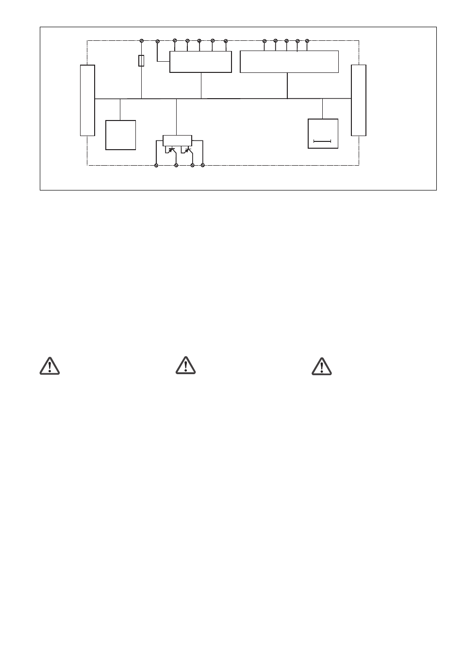
Innenschaltbild
Internal wiring diagram
Schéma interne
Betriebsarten:
• Einkanaliger Betrieb: EN 60204-1 (VDE
0113-1) und IEC 60204-1, keine Re-
dundanz im Eingangskreis, Erdschlüsse
im Tasterkreis werden erkannt.
• Zweikanaliger Betrieb: redundanter Ein-
gangskreis, Erdschlüsse im Tasterkreis
und Querschlüsse zwischen den Taster-
kontakten werden erkannt.
• Automatischer Start: Gerät ist aktiv,
sobald Eingangskreis geschlossen ist.
• Manueller Start: Gerät ist erst dann aktiv,
wenn ein Starttaster betätigt wird.
Dadurch ist ein automatischer Start des
Schaltgeräts nach Spannungsausfall und
-wiederkehr ausgeschlossen.
• Manueller Start mit Überwachung:
Gerät ist erst aktiv, wenn der Starttaster
betätigt und wieder losgelassen wurde.
Sicherheitsschaltgerät montieren
Achtung! Montieren Sie das
Sicherheitsschaltgerät in einen
Schaltschrank mit einer Schutzart von
mindestens IP54.
• Befestigen Sie das Gerät mit Hilfe des
Rastelements auf der Rückseite auf einer
Normschiene.
• Montieren Sie das Gerät auf eine waagrech-
te Tragschiene. Bei anderen Einbaulagen
können die in den techn. Daten angegebe-
nen Werte für das Schaltvermögen nicht
eingehalten werden.
• Maximalbestückung eines PNOZpower-
Systems:
- 1 Basisgerät PNOZ p1vp
- max. 4 Erweiterungsmodule, die
unverzögert angesteuert werden, links
vom Basisgerät montieren
(siehe Fig. "Montage des PNOZ p1vp")
- max. 4 Erweiterungsmodule, die
verzögert angesteuert werden, rechts
vom Basisgerät montieren
(siehe Fig. "Montage des PNOZ p1vp")
- max. 2 Netzgeräte PNOZ pps1p
Wenn Sie das Netzgerät pps1p verwen-
den, benötigen die Erweiterungsgeräte
mit verzögerter und unverzögerter
Ansteuerung jeweils ein Netzgerät
(siehe Fig. "Montage des PNOZ p1vp").
• Auf der Geräterückseite des PNOZ p1vp
befinden sich 2 Buchsen. Das Basisgerät
PNOZ p1vp wird mit den Erweiterungs-
modulen über die mitgelieferten Steck-
brücken verbunden.
Ausgang
Output
Sortie
A2 (0V)
Y32 Y35
Y2
S33
S22
S12 S52
S11
A1 (+)
Y31
Y30
S21
Y1
S34
Eingangskreise
Input circuit
circuit d'entree
PNOZpower-Bus
Start-/Rückführkreis
Reset circuit/feedback control loop
circuit de réarmement/boucle de retour
S37
PNOZpower-Bus
Ausgang
Output
Sortie
Operating modes:
• Single-channel operation: EN 60204-1
(VDE 0113-1) and IEC 60204-1, no input
circuit redundancy, earth faults in the
button circuit will be recognised.
• Dual-channel operation: redundant input
circuit, earth faults in the button circuit
and short circuits between the button
contacts will be detected.
• Automatic reset: Unit is active as soon
as the input circuit is closed.
• Manual reset: Unit is only active when a
reset button has been pressed. Automatic
activation following a loss/return of supply
voltage is thereby prevented.
• Monitored manual start: Unit is not
active until the reset button has been
operated and then released.
Installing the safety relay
Caution! The safety relay should be
installed in a control cabinet with a
protection type of at least IP54.
• Use the notch on the rear of the unit to
attach it to a DIN rail.
• Fit the unit to a horizontal DIN rail. In
other mounting positions, the values given
in the technical details for the switching
capability may not be achieved.
• Maximum hardware in a PNOZpower
system:
- 1 PNOZ p1vp base unit
- max. 4 expansion modules that are
controlled instantaneously, install to the
left of the base unit
(see Fig. "Installing the PNOZ p1vp")
- max. 4 expansion modules that are
controlled with a delay time, install to
the right of the base unit
(see Fig. "Installing the PNOZ p1vp")
- max. 2 PNOZ pps1p power supplies
If you are using the pps1p power
supply, the instantaneous and delayed
expansion modules will each need a
power supply
(see Fig. "Installing the PNOZ p1vp").
• There are 2 sockets on the rear of the
PNOZ p1vp. Connect the PNOZ p1vp
base unit to the expansion modules using
the jumpers supplied.
Modes de fonctionnement :
• Commande par 1 canal : EN 60204-1 (VDE
0113-1) et IEC 60204-1, circuit d’entrée non
redondant, reconnaissance des mises à la
terre dans les circuits d’entrée.
• Commande par 2 canaux : circuit d’entrée
redondant. Les mises à la terre dans les
circuits d’entrée et les courts-circuits entre
les contacts sont détectés.
• Réarmement automatique : l’appareil est
actif dès la fermeture du circuit d’entrée.
• Réarmement manuel : l’appareil n’est activé
qu’après l’actionnement d’un poussoir de
réarmement. Cela permet d’exclure un
réarmement automatique du relais après
coupure/rétablissement du courant.
• Réarmement manuel auto-contrôlé :
l’appareil n’est activé qu’après le relâche-
ment du poussoir de réarmement.
Installer le bloc logique de sécurité
Attention ! Montez le bloc logique de
sécurité dans une armoire ayant un
indice de protection d’au moins IP54.
• Montez l’appareil sur un rail normalisé à l’aide
du système de fixation situé au dos de
l’appareil.
• Montez l’appareil sur un profilé support
horizontal. Les autres positions de montage ne
permettent pas de respecter les valeurs de
commutation indiquées dans les
caractéristiques techniques.
• Équipement maximal d’un système
PNOZpower :
- 1 appareil de base PNOZ p1vp
- max. 4 modules d’extension à pilotage
instantané, à monter à gauche du module
de base
(voir fig. "Montage du PNOZ p1vp")
- max. 4 modules d’extension à pilotage
temporisé, à monter à droite du module de
base
(voir fig. "Montage du PNOZ p1vp")
- max. 2 modules d’alimentation
PNOZ pps1p
Si vous utilisez le module d’alimentation
pps1p, les modules d’extension à pilotage
immédiat et temporisé ont besoin chacun
d’un module d’alimentation
(voir fig. "Montage du PNOZ p1vp").
• La face arrière du PNOZ p1vp comporte 2
douilles. L’appareil de base PNOZ p1vp est
relié aux modules d’extension par le biais des
cavaliers de pontage fournis.