Pilz PNOZ e6vp 24VDC 4n/o 1so 1so t User Manual
Page 7
- 7 -
➀
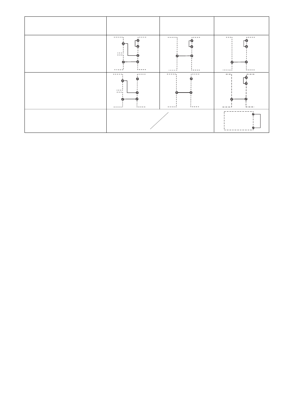
Die Beschaltung von Y4 muss wie hier
dargestellt vorgenommen werden
(abweichend von der Darstellung beim
Eingangskreis).
➀
Y4 must be wired as shown here
(deviates from the diagram shown for the
input circuit).
➀
Le câblage de Y4 doit être exécuté
comme l’indique le schéma (par
dérogation au schéma du circuit d’entrée).
Betrieb
Beim Start erkennt das Gerät die eingestellte
Betriebsart. In der dafür benötigten Zeit blinkt
die LED "POWER".
Das Gerät ist betriebsbereit, wenn die LED
"POWER" dauerhaft leuchtet.
Statusanzeigen
• "CH.1" bzw. "CH.2" leuchtet: Sicherheits-
ausgang 14 bzw. 24 leitet, die Sicher-
heitskontakte 33-34, 43-44, 53-54 und
63-64 sind geschlossen.
• "CH.1" bzw. "CH.2" erlöschen: Sicherheits-
ausgang 14 bzw. 24 sperrt, die Sicher-
heitskontakte 33-34, 43-44, 53-54 und
63-64 sind geöffnet.
Fehler - Störungen
Fehleranzeige
• LED "CH.1" oder LED "CH.2" blinkt:
Interner Fehler, Verdrahtungsfehler oder
Querschluss
• "CH.1" und CH.2" blinken abwechselnd:
- Rückführkreis beim Start offen
Abhilfe: Rückführkreis schließen,
Eingangskreis öffnen und Low-Signal
am ODER-Eingang anlegen
- nur ein Kanal des Eingangskreises offen
(Teilbetätigung)
Abhilfe: beide Kanäle des Eingangs-
kreises öffnen
Gerät wieder starten
Wenn Sie den Fehler behoben haben,
starten Sie das Gerät neu, indem Sie die
Spannungsversorgung kurz ausschalten und
wieder einschalten.
Abbruch der Verzögerungszeit
Im Fehlerfall können die rückfallverzögerten
Kontakte vor Ablauf der Verzögerungszeit
öffnen.
(fortsetzung auf der nächsten Seite)
Operation
The unit detects the set operating mode on
start-up. During this time the “POWER” LED
will flash.
The unit is ready for operation when the
“POWER” LED is lit continuously.
Status indicators
•„CH.1“ and/or „CH.2“ lights: Safety output
14 and/or 24 is enabled, the safety
contacts 33-34, 43-44, 53-54 and
63-64 are closed.
• „CH.1“ and/or „CH.2“ goes out: Safety
output 14 and/or 24 disabled, the safety
contacts 33-34, 43-44, 53-54 and
63-64 are open.
Faults
Fault indicator
• LED „CH.1“ or LED „CH.2“ flashes:
Internal error, wiring error or short across
contacts
• „CH.1“ and CH.2" flashing alternately:
- Feedback loop open at start
Remedy: Close fedback loop, open
input circuit and enter low signal at OR
input
- Only one channel of the input circuit is
open (partially operated)
Remedy: Open both channels of the
input circuit
To restart the unit
Once you have rectified the fault, restart the
unit by briefly switching off the power supply
and switching it back on.
Delay time aborted
In the case of an error, the delay-on de-
energisation contacts may open before the
delay time has elapsed.
(Continued on next page)
Fonctionnement
Au réarmement, l’appareil identifie le mode
de fonctionnement prédéfini. Pendant la
durée nécessaire au réarmement la LED
„POWER“ clignote.
L’appareil est prêt à fonctionner lorsque la
LED „POWER“ reste allumée.
Affichage d'état
• „CH.1“ et/ou“CH.2" sont allumées : sorties
de sécurité 14 et/ou 24 sont passantes,
les contacts de sécurité 33-34, 43-44, 53-
54 et 63-64 sont fermés.
• „CH.1“ et/ou „CH.2“ sont éteintes : sorties
de sécurité 14 et/ou 24 sont bloquées, les
contacts de sécurité 33-34, 43-44, 53-54 et
63-64 sont ouverts.
Erreurs - Défaillances
Affichage des erreurs
• LED „CH.1“ ou LED „CH.2“ clignote :
défaut interne, erreur de câblage ou court-
circuit
• „CH.1“ et CH.2" clignote par alternance :
- boucle de retour ouverte lors du
réarmement
Aide : fermer la boucle de retour , ouvrir
les canaux d’entrée et appliquer un
signal Low sur l’entrée OU
- un seul canal d’entrée a été ouvert
Aide : ouvrir les 2 canaux d’entrée
Redémarrer l’appareil
Une fois l’erreur supprimée, redémarrez
l’appareil en coupant brièvement l’alimenta-
tion en tension puis en la réactivant.
Temporisation interrompue
En cas de défaut, les contacts temporisés à
la retombée peuvent s’ouvrir avant
l’écoulement de la temporisation.
(Suite à la page suivante)
Y4
S36
14/24
PNOZ e6vp
Unit 1
AND
Sicherheitsausgang 14 verzögert
Safety output 14 delayed
Sortie de sécurité 14 temporisée
S36
A1
Y4
S35
14/24
PNOZ e6vp
Unit 1
OR
S21
Y4
S35
14/24
PNOZ e6vp
Unit 1
OR
S11
Y4
S36
S35
14/24
14/24
PNOZ e6vp
Unit 1
Unit 2
AND
OR
Y4
S36
S35
14/24
14/24
PNOZ e6vp
Unit 1
Unit 2
AND
OR
A1
Eingangskreis
Input circuit
Circuit d’entrée
UND und ODER
UND and OR
ET et OU
ODER
OR
OU
ohne Querschlusserkennung
without detection of shorts across contacts
sans détection des court-circuits
mit Querschlusserkennung
with detection of shorts across contacts
avec détection des court-circuits
➀
➀
Y4
S36
14/24
PNOZ e6vp
Unit 1
AND
A1
UND
UND
ET
➀
➀