Vortech 2003-2004 Chevrolet SS User Manual
Page 40
22
P/N: 4GL020-015
©2008 Vortech Engineering, LLC
All Rights Reserved, Intl. Copr. Secured
08OCT08 GM Trk/H2(4GL..015v5.0)
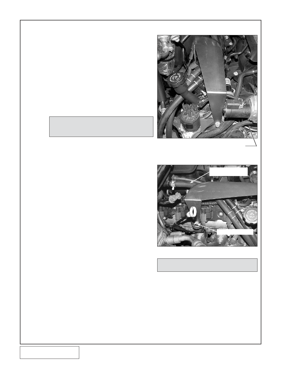
14. CHARGE COOLER INSTALLATION
A. Remove the screw from the front of the pas-
senger side head. Remove the stud located
between the middle coil packs on the passen-
ger side valve cover, below the white electri-
cal connector. (See Figs. 14-a, 14-b.)
B. Install the charge air cooler support using the
fasteners supplied. (See Figs. 14-a, 14-b.)
Apply adhesive foam to the top of the support
bracket where the charge air cooler rests.
Make sure all hoses and wires are clear from
the bracket edges.
Cannot bend trans lines: Remove the
bracket holding the lines on the passenger’s
side valve cover. Secure the lines underneath
the wiring harness with zip-ties.
Fig. 14-a
Fig. 14-b
On the H2 Hummer, use the supplied
10mm x 1.5 screw, washer and .975"
spacer in place of EGR equipment
STUD TO BE REMOVED
SECURE HOSES AWAY
FROM BRACKET
C. Slightly bend both the transmission and
engine oil dipsticks up and away to give
clearance for the charge air cooler.
D. Install the 1/2"NPT x 3/4 90° and straight
brass fittings into the charge air cooler using
thread sealant on the threads. (See Fig.
14-e.)
E. Install the S-hose and the 90° hose onto the
CAC, then set on support.
F. Attach the short 90° formed hose to the
straight barbed fitting on the charge cooler.
(See Fig 14-e).
G. Set the charge air cooler on the support with
the 90° brass fitting in the upper left corner
facing toward the passenger’s side. Using the
2-3/4" sleeves and #44 hose clamps, connect
discharge tube “A” to the discharge of the
supercharger and to the inlet of the charge air
NOTE: On H2 Hummer and '04 SS, '06 Denali installations,
there will be no EGR assembly. Use the supplied
10mm x 1.5" screw, washer and .975" spacer in its
place. (See Fig. 14-a.)
NOTE: It will be necessary to trim 1/2” from the 2.75” end
of the reducer sleeve for proper fit.