Vortech 2003-2004 Chevrolet SS User Manual
Page 38
20
P/N: 4GL020-015
©2008 Vortech Engineering, LLC
All Rights Reserved, Intl. Copr. Secured
08OCT08 GM Trk/H2(4GL..015v5.0)
C. Install the supplied 4GL012-090 alum inlet
duct to the end of the molded inlet duct using
Ø3.5” x 2” sleeve and two #56 hose clamps.
(See Fig 12.D-d)
D. Secure the Ø3.5” x 9” long flex hose to the
alum. inlet duct using a #52 hose clamp. (See
Fig 12.D-d).
E. Install the 3/4"NPT x 1” 90° fitting and the 3/8
NPT x 3/8 barb 90° fitting in the 4FA012-013
inlet duct. (See Fig 12.D-e).
F. Secure the 4FA012-013 duct to the S/C using
a Ø3.5 x 2” sleeve and two #56 hose clamps.
G. Connect the Flex hose to the 4FA012-013
duct and secure using a #52 hose clamp.
H. Slight bending of the brake lines may be nec-
essary to clear the inlet ducts.
I. Cut the supplied 45° hose so the one leg is
approx. 2.75” long and one is approx. 1.5”
long. (See Fig 12.D-f).
J. Attach the long end of the hose to the plastic
inlet duct and secure with the hose clamp that
is provided. Install the compressor by pass to
the open end of the hose just installed and
secure with a hose clamp.
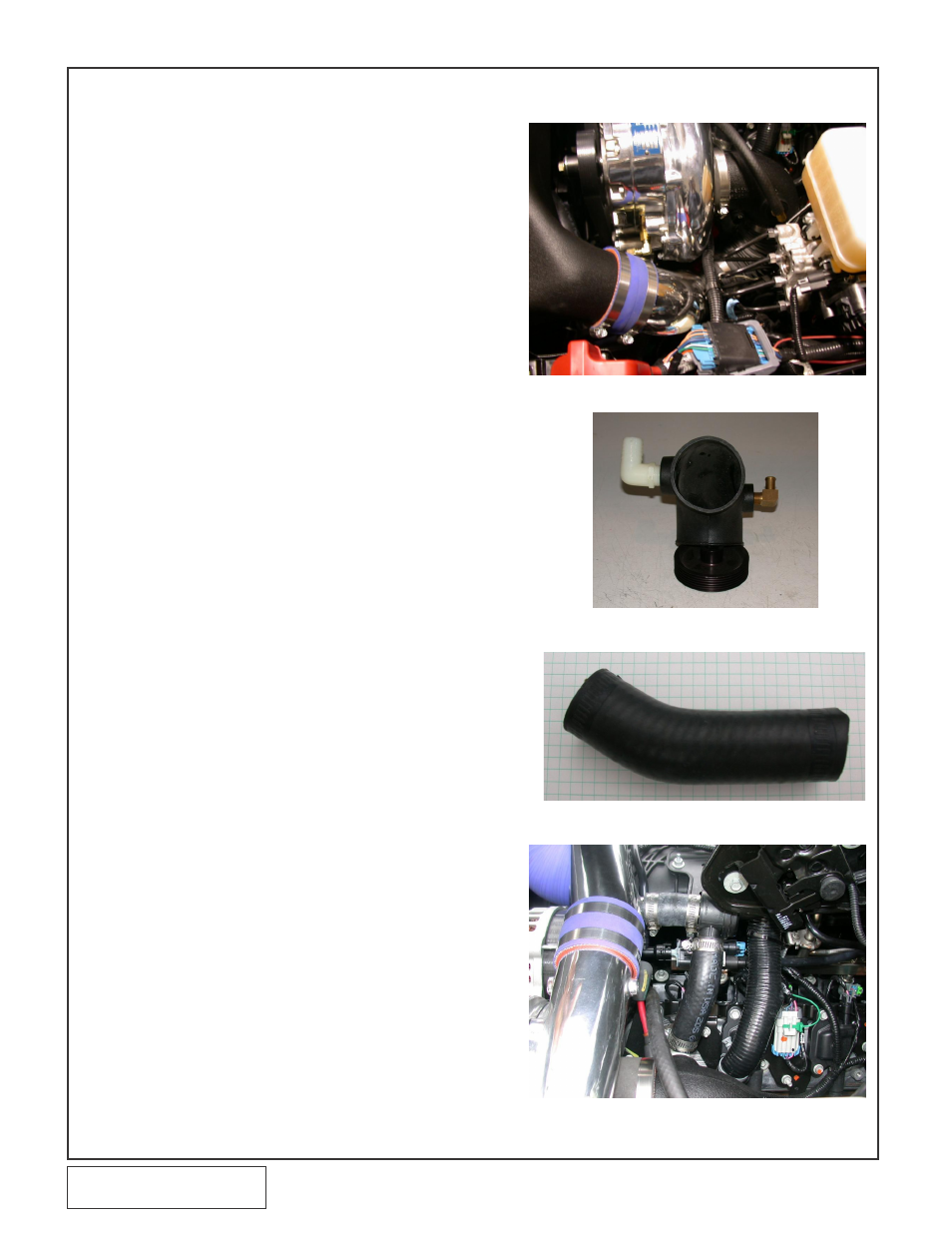
K. Using a length of hose cut from the previously
install formed hose connect the compressor
bypass valve to the discharge duct coming
out of the Supercharger. (See Fig 12.D-g)
L. Attach the 5/32 hose installed in an earlier
step to the inlet port of the compressor
bypass..
Fig. 12.D-d
Fig. 12.D-e
Fig. 12.D-f
Fig. 12.D-g
12.D 2008 H2 HUMMER INLET DUCT INSTALLATION con't