LINK Systems LinkNet I User Manual
Page 42
LinkNet
A.2
manual rev 2.1 March 25, 1999
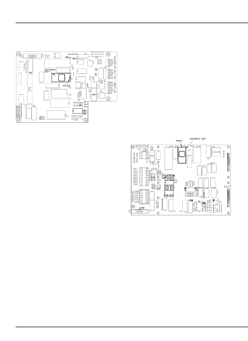
Figure A.1:
System 1100 OIT Circuit Board
A.2.2 System 1100 Motherboard Software
Upgrade Procedure
@
Review section A.1 for chip changing rules!
@
Turn off the power to the System 1100.
@
Open the front door of the System 1100
enclosure.
@
Remove the five pan-head screws holding down
the channel 1 and 2 dual channel card (the card
in the bottom of the unit that has the channel 1
and channel 2 strain gauges plugged into it ).
Remove the channel card by pulling on the
handle on the card.
@
Using Figure A.2, locate the software chip on
the 1100-1 circuit board and remove it.
@
Install the new software chip labeled “1100-2-
MB” in the socket for a two channel unit, or the
chip labeled “1100-4-MB” for a four channel
unit. A 4 channel chip in a 2 channel
motherboard or a 2 channel chip in a 4 channel
motherboard will prevent the unit from working
correctly!
@
Install the Channel 1 and 2 dual channel card -
Be sure not to leave any lockwashers or screws
loose in the unit!
@
Restore power to the System 1100.
@
Make sure that the System 1100 resets. You
should see a screen that look similar to:
LINK SYSTEMS 1100
V2.7 OIT V2.5MB
on the LCD for about 5 seconds after power-up.
The main menu should then appear.
Figure A.2:
System 1100 Motherboard Circuit
Board