Aircraft flight trimming chart, Test procedure, Observations – HITEC Eclipse 7 User Manual
Page 27: Adjustments
Aircraft(ACRO) Section
27
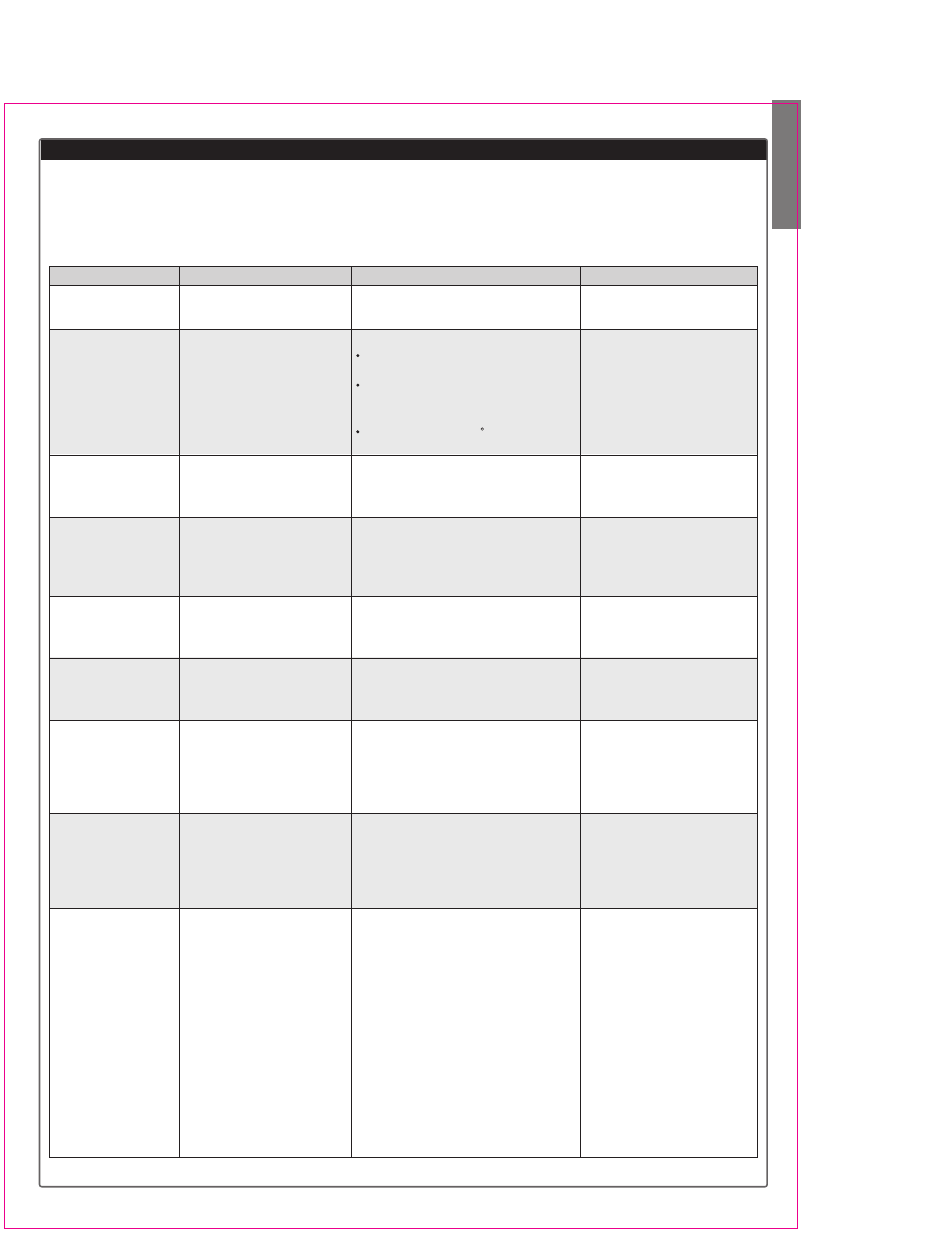
The following chart may be used to systematically set up and trim a model for straight flight and aerobatic
maneuvers. Please note that for best results, trimming should be done in near-calm conditions. Before you decide
to make a change, be sure to try the test several times before making adjustments. If any changes are made, go
back through the previous steps and verify that they are not also affected. If they are, make further adjustments as
necessary.
To test for ...
1. Control neutrals
2. Control throws
3. Decalage
4. Center of Gravity
5. Tip weight
(coarse adjustment)
6. Side Thrust & Warped
Wing
7. Up/Down Thrust
8. Tip weight
(fine adjustment)
9. Aileron differential
Test Procedure
Fly the model straight and level
Fly the model and apply full
deflection of each control in turn
Power off vertical dive(crosswind if
any). Release controls when
model vertical (elevator trim must
be neutral)
Method 1: Roll into near vertically-
banked turn.
Method 2: Roll model inverted
Fly model straight & level upright.
Check aileron trim maintains level
wings. Roll model inverted, wings
level. Release aileron stick.
Fly model away from you into any
wind. Pull it into a vertical climb,
watch for deviations as it slows
down.
Fly the model on normal path into
any wind, parallel to strip, at a
distance of around 100 meters from
you (elevator trim should be neutral
as per Test 3). Pull it into a vertical
climb & neutralize elevator
Method 1: fly the model as per Test
6 and pull into a reasonably small
diameter loop (one loop only)
Method 2: fly the model as per Test
6 and then push into an outside
loop (one only, fairly tight)
Method 1: fly model toward you &
pull into a vertical climb before it
reaches you. Neutralize controls,
then half-roll the model.
Method 2: fly model on normal pass
and do three or more rolls
Method 3: fly the model straight and
level and gently rock the aileron
stick back and forth
Observations
Use the transmitter trims for hands-off
straight & level flight.
Check the response of each control
Aileron high-rate: 3 rolls in 4 seconds;
low-rate: 3 rolls/6 sec
Elevator high-rate: to give a smooth
square corner; low-rate gives approx.
130 ft diameter loop
Rudder: high-rate 30-35 for stall turns;
low rate maintains knife-edge
A. Model continues straight down
B. Model starts to pull out (nose up)?
C. Model starts to tuck in (nose down)?
A1. Nose drops B1. Tail drops
A2. Lots of forward stick (down elevator)
required to maintain level flight
B2. No forward stick (down elevator) required
to maintain level flight, or model climbs
A. Model does not drop a wing.
B. Left wing drops.
C. Right wing drops.
A. Model continues straight up.
B. Model veers left
C. Model veers right
D. Model rolls right
A. Model continues straight up
B. Model pitches up (goes toward
top of model)
C. Model pitches down
(goes toward bottom of model)
A. Model comes out with wings level
B. Model comes out right wing low
C. Model comes out left wing low
A. No heading changes
B. Heading change opposite to roll command
(i.e. heading veers left after right roll)
C. Heading change in direction of roll
command
A. Roll axis on model centerline
B. Roll axis off to same side of model as roll
command (i.e. right roll, roll axis off right
wing tip)
C. Roll axis off to opposite side of model as
roll command
A. Model flies straight ahead without yawing
B. Model yaws away from roll command
(i.e. right roll, yaw left)
C. Model yaws towards roll command
(i.e. right roll, yaw right)
Adjustments
Change electronic subtrims or
adjust clevises to center
transmitter trims.
Change EPA (for high rates),
and Dual Rate settings (for low
rates) to achieve desired
responses.
A. No adjustment
B. Reduce incidence
C. Increase incidence
A. Add weight to tail
B. Add weight to nose
A. No adjustment
B. Add weight to right tip.
C. Add weight to left tip.
A. No adjustment
B. Add right thrust
C. Reduce right thrust
D. Put trim tab under left wing tip *
A. No adjustment
B. Add down thrust
C. Reduce down thrust
A. No adjustment necessary
B. Add weight to left tip
C. Add weight to right tip
A. Differential settings OK
B. Increase differential
C. Decrease differential
A. Differential settings OK
B. Increase differential
C. Decrease differential
A. Differential settings OK
B. Increase differential
C. Decrease differential
Aircraft Flight Trimming Chart